Electricsuturing needle holder of peritoneoscope

A laparoscopic, electric technology, applied in the medical field, can solve the problems of sutured tissue pulling, affecting the safety and efficiency of surgery, limited field of view, etc., and achieves the effect of high suture efficiency

Pending Publication Date: 2019-04-16
THE FIRST AFFILIATED HOSPITAL OF ZHENGZHOU UNIV
View PDF0 Cites 3 Cited by
  • Summary
  • Abstract
  • Description
  • Claims
  • Application Information

AI Technical Summary

Problems solved by technology

[0002] With the deepening of the concept of minimally invasive surgery and the advancement of instrumental surgery and surgical technology, TV-assisted endoscopic surgery has been widely used in clinical practice; Needle holders are routinely used needle holders during minimally invasive surgery; due to the small incision and limited field of view of minimally invasive surgery, multiple instruments are often used to cooperate with the operation during the operation, and surgical instruments are frequently replaced. It is a long-handled forceps structure, and continuous suturing needs to go through: holding the needle - entering the body cavity - inserting the needle - adjusting the suture depth - withdrawing the needle - pulling out the needle - taking out the body cavity - re-holding the needle, the steps are cumbersome; Going in and out of the surgical field will inevitably block the line of sight and affect the surgical operation; in addition, in some special parts, due to the limited space, it is difficult to grasp the suture depth when inserting the needle with one hand under the endoscope, and it is easy to over-stretch the sutured tissue, resulting in tearing or tearing. Bleeding, affecting the safety and efficiency of surgery

Method used


Image

  • Electricsuturing needle holder of peritoneoscope
  • Electricsuturing needle holder of peritoneoscope

Examples


Embodiment Construction

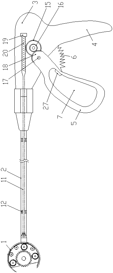
[0017] Such as figure 1 with figure 2 As shown, the electric laparoscopic suture needle holder of the present invention includes an electric suture head 1, a forceps body 2 and a handle seat 3, the forceps body 2 is a hollow tubular structure, and the electric suture head 1 is arranged on the forceps body 2, the handle base 3 is arranged on the rear end of the pincer body 2, and the bottom of the handle base 3 is provided with a handle, the handle includes a first handle 4 and a second handle 5, and the first handle 4 is fixed on The bottom of the rear side of the handle base 3 extends downwards, the upper end of the second handle 5 is hinged on the bottom of the handle base 3 and is positioned at the front side of the first handle 4, the first handle 4 and the second handle The opposite surface of 5 is provided with a return spring 6, and the second pincer handle 5 is provided with a port 7 for hand passing through;

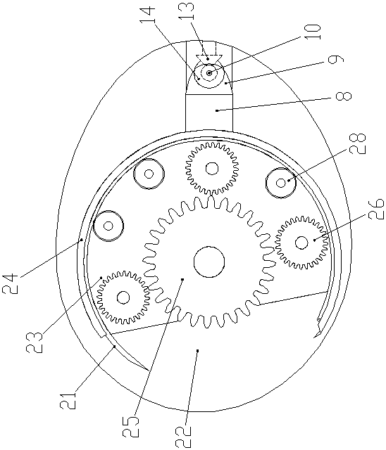
[0018] The electric suture head 1 includes a suture hea...


PUM


Abstract

The invention discloses an electric suturing needle holder of aperitoneoscope. The electric suturing needle holder of theperitoneoscope comprises an electric suturing head part, a clamp rod body and aclamp handle base, the clamp rod body is of a hollow tube body structure, and the electric suturing head part is arranged at the front end of the clamp rod body; the clamp handle base is arranged atthe back end of the clamp rod body, a clamp handle is arranged at the bottom of the clamp handle base and comprises a first clamp handle and a second clamp handle, the first clamp handle is fixed to the bottom of the back side of the clamp handle base and extends downward, and the upper end of the second clamp handle is hinged to the bottom of the clamp handle base and located on the front side ofthe first clamp handle; in collusion, the suturing work is completed through a series of mechanical assemblies, the suturing efficiency is high, and after one-time suturing, a suture needle is in a staying state directly; the time of clamping the suture needle again and adjusting the posture is saved, quick and continuous suturing can be achieved, and in addition, a suturing head steering drivingmechanism is arranged and used for driving steering of the suturing head part so that the suturing head part can conduct suturing from the best angle.

Description

technical field [0001] The invention belongs to the field of medical technology, in particular to an electric laparoscopic suture needle holder. Background technique [0002] With the deepening of the concept of minimally invasive surgery and the advancement of instrumental surgery and surgical technology, TV-assisted endoscopic surgery has been widely used in clinical practice; Needle holders are routinely used needle holders during minimally invasive surgery; due to the small incision and limited field of view of minimally invasive surgery, multiple instruments are often used to cooperate with the operation during the operation, and surgical instruments are frequently replaced. It is a long-handled forceps structure, and continuous suturing needs to go through: holding the needle - entering the body cavity - inserting the needle - adjusting the suture depth - withdrawing the needle - pulling out the needle - taking out the body cavity - re-holding the needle, the steps are...

Claims


Application Information

Patent Timeline
Patent Type & Authority Applications(China)
IPC IPC(8): A61B17/062
CPCA61B17/0625
Inventor 徐焕焕
Owner THE FIRST AFFILIATED HOSPITAL OF ZHENGZHOU UNIV
Why Eureka
Try Eureka