
Ink box chip, light emitting display method thereof and ink box

An ink cartridge chip, light-emitting display technology, applied in printing and other directions, can solve the problems of easy error, low production efficiency, inability to detect light emitting diode light, etc., and achieve the effect of reducing production cost and high production efficiency

Active Publication Date: 2013-05-08
ZHUHAI TIANWEI TECH DEV CO LTD
View PDF16 Cites 11 Cited by
  • Summary
  • Abstract
  • Description
  • Claims
  • Application Information

AI Technical Summary

Problems solved by technology

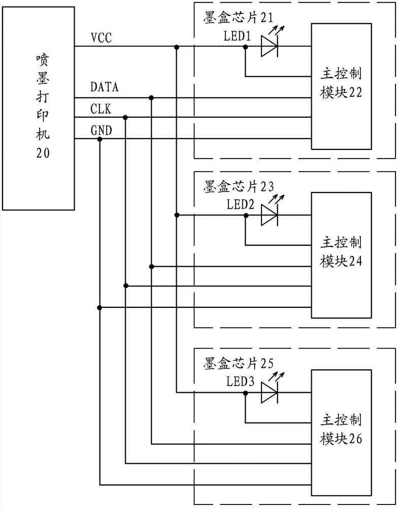
[0016] Like this, just require that ink cartridge chip must be installed on the correct ink cartridge, for example, inkjet printer 20 detects successively according to the order of red ink cartridge, blue ink cartridge, yellow ink cartridge, then the chip that is stored with red ink cartridge identification code must follow to red ink cartridge. Above, once the ink cartridge chip is installed incorrectly, the inkjet printer 20 will not be able to detect the light emitted by the light-emitting diode on the ink cartridge chip, and the inkjet printer 20 will judge that the red ink cartridge is not installed correctly, and the printing operation cannot be performed
[0017] Therefore, when installing the ink cartridge chip into the ink cartridge, it is necessary to carefully check the applicable ink cartridge of the ink cartridge chip, resulting in a large workload for installing the ink cartridge chip, low production efficiency, and error-prone, which affects the use of the ink cartridge

Method used


Image

  • Ink box chip, light emitting display method thereof and ink box
  • Ink box chip, light emitting display method thereof and ink box
  • Ink box chip, light emitting display method thereof and ink box

Examples


Embodiment Construction

[0035] The ink box chip of the present invention is installed on the ink box used by the ink jet printer, receives the signal output by the ink jet printer, and returns a corresponding signal to the ink jet printer according to the output signal of the ink jet printer.

[0036] Embodiment of the ink cartridge chip and its light-emitting display method:

[0037] like Figure 4 As shown, multiple ink cartridges are installed on the inkjet printer 30, and an ink cartridge chip is installed on each ink cartridge, such as ink cartridge chips 31, 34, 37, etc., each ink cartridge chip has a substrate, and one side of the substrate is provided as The multiple electrical contacts of the communication unit are used to connect with the electrical contacts of the inkjet printer 30 , and the other side of the substrate is provided with an electronic module.

[0038] Of course, if the ink cartridge chip is a wireless chip, the communication module is an antenna for receiving wireless signa...


PUM


Abstract

The invention provides an ink box chip, a light emitting display method thereof and an ink box. The ink box chip comprises a substrate which is provided with a communication unit and an electronic module, and further provided with a light emitting diode (LED) which is controlled to light by the electronic module. The electronic module comprises a master control module which receives signals which is output by the communication unit, wherein the electronic module is further provided with a light emitting control module which receives light emitting control signals output by the communication unit, and when receiving an order of long bright light emitting signals of the LED of any ink box chips, the light emitting control module controls the LED to light in a long bright mode. The light emitting display method is the method that after the above ink box chip receives the light emitting control signals, the LED is controlled to light. The ink box is provided with a shell box, and the ink box chip is arranged on the outer wall of the shell body. According to the ink box chip, the light emitting display method thereof and the ink box, the work amount of mounting the ink box chip can be reduced, the work efficiency of mounting the ink box chip can be improved, and meanwhile the work of an ink-jet printer can be guaranteed.

Description

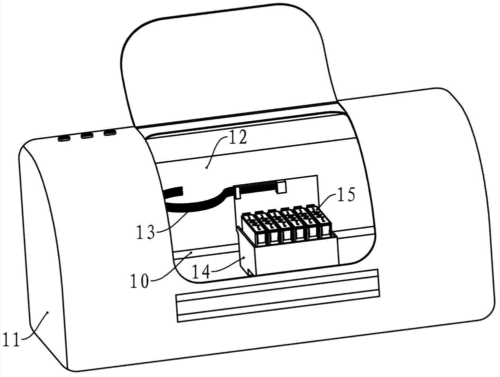
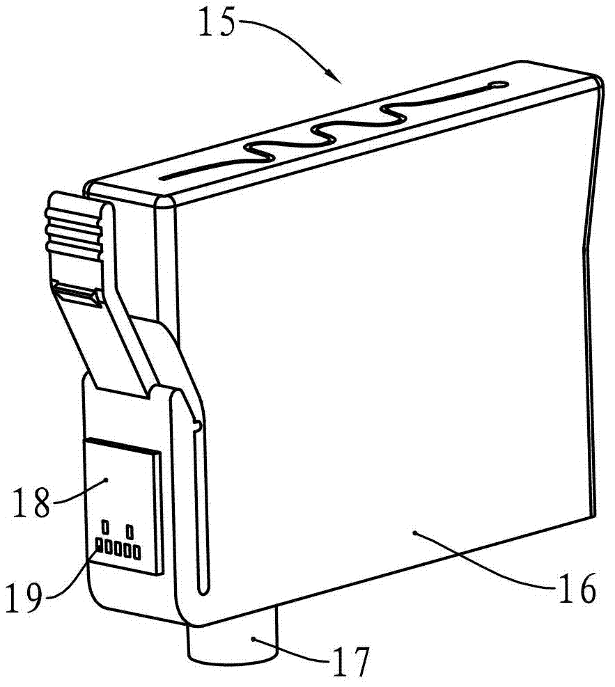
technical field [0001] The invention relates to the field of printing consumables, in particular to an ink cartridge chip applied to an ink cartridge, an ink cartridge with the ink cartridge chip, and a light-emitting display method for the ink cartridge chip. Background technique [0002] Inkjet printers are common printers that provide great convenience for modern offices. Inkjet printers use an ink cartridge containing ink as a consumable container to eject ink onto paper to form text or patterns that need to be printed on the paper. [0003] see figure 1 , an existing color inkjet printer has a casing 11, figure 1 The inkjet printer is shown with the chassis 11 omitted. The machine core 12 of ink-jet printer is provided with in the casing 11, and is provided with a slide bar 10, and printing word car 14 is in motor ( figure 1 (not visible in the middle) is driven to reciprocate along the slide bar 10. Printing word car 14 is provided with adapter plate ( figure 1 n...

Claims


Application Information

Patent Timeline
IPC IPC(8): B41J2/175
CPCB41J2/175B41J2/17553B41J2/17546
Inventor 袁珍平
Owner ZHUHAI TIANWEI TECH DEV CO LTD
Learn More