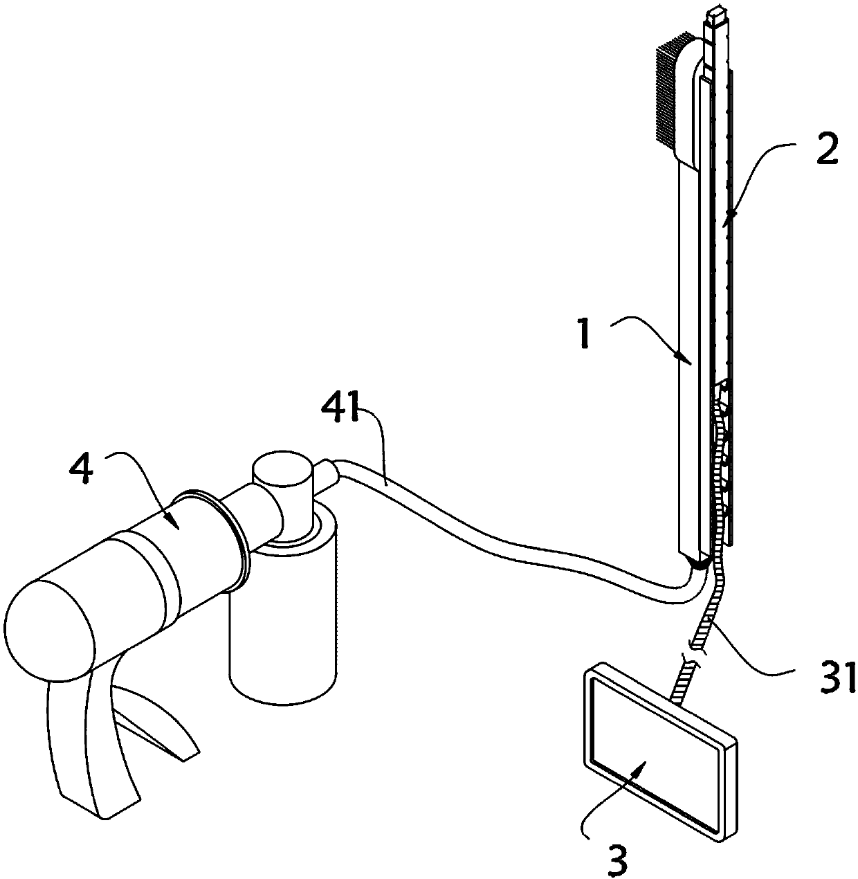
Visual disposable brush rod for oral nursing of critically ill patient
An oral care, disposable technology, applied in the directions of oral mirrors, brushes, applications, etc., can solve the problems that the nursing staff cannot intuitively observe the inside of the patient's mouth, suck oral care, and increase the number of patients, so as to improve the service life, The effect of reducing complications and reducing workload
- Summary
- Abstract
- Description
- Claims
- Application Information
AI Technical Summary
Benefits of technology
Problems solved by technology
Method used
Image
Examples
Embodiment 1
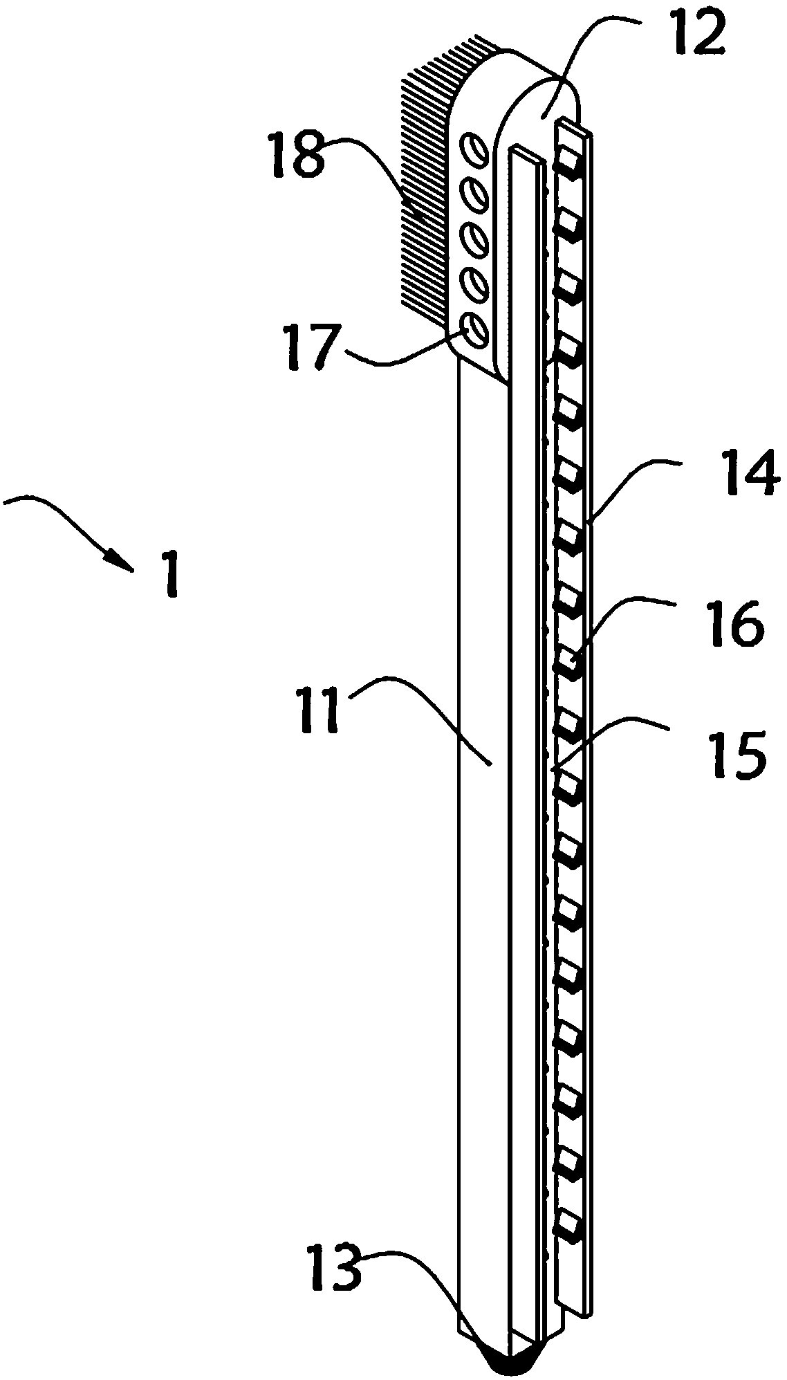
[0035] Such as Figure 1-4 As shown, the visual disposable brush stick for oral care of critically ill patients includes a brush stick body 1 and a brush stick side body 2 installed on one side of the brush stick body 1. The brush stick body 1 includes a suction channel plate 11, and A brush head 12 is installed on the top, and a suction pipe interface 13 is provided at the bottom of the suction pipe plate 11. A pair of mounting plates 14 are installed on the end of the suction pipe plate 11 close to the side body 2 of the brush rod. Between the two mounting plates 14 and the suction pipe plate 11 A mounting groove 15 is formed between them, and a plurality of limiting devices 16 are installed on the inner wall of the mounting plate 14. The limiting device 16 includes an oblique block 161, and the two ends of the bottom of the oblique blocking block 161 are respectively provided with mounting feet 162, two mounting feet 162 There is an arc groove 163 between them, the inner wa...
Embodiment 2
[0041] As a second embodiment of the present invention, in order to facilitate the visual operation of the patient's oral cavity during oral care, the inventors set a micro-camera 24 on the brush stick side body 2, as a preferred embodiment, as Figure 5-6As shown, the brush bar side body 2 includes a probe channel plate 21, a plurality of card slots 22 are respectively opened on both sides of the probe channel plate 21, a wire port 23 is provided at the bottom of the probe channel plate 21, and a The micro camera 24 has a lens 25 embedded in the outer surface of the micro camera 24, and a plurality of lamp beads 26 are installed on the side of the micro camera 24 close to the lens 25. The inside of the probe channel plate 21 is a hollow structure, and the size of the connecting shaft 165 and the slot 22 The size matches.
[0042] In this embodiment, the size of the probe channel plate 21 matches the size of the installation groove 15 , so that the probe channel plate 21 can b...
Embodiment 3
[0046] As a third embodiment of the present invention, in order to facilitate the protection of the internal sealing environment of the brush rod body 1, the inventors set up a gas blocking mechanism 19, as a preferred embodiment, such as Figure 7 As shown, the gas blocking mechanism 19 includes a gas blocking cylinder 191, one end of the gas blocking cylinder 191 is provided with a plug plate 192, the inner wall of the gas blocking cylinder 191 is provided with a linear slide rail 193, and one end of the linear slide rail 193 is provided with an arc-shaped slide rail 194, a rotary handle 195 is installed on the outer surface of the plug plate 192, a sealing ring 196 is installed on the inner wall of the plug plate 192, an inner cylinder 197 is installed on the side of the plug plate 192 near the sealing ring 196, and the upper and lower ends of the inner cylinder 197 are respectively provided with A plurality of ventilation holes 198, the outer walls of both sides of the inne...
PUM
 Abstract
Description
Claims
Application Information
 - R&D
- Intellectual Property
- Life Sciences
- Materials
- Tech Scout
- Unparalleled Data Quality
- Higher Quality Content
- 60% Fewer Hallucinations
Browse by: Latest US Patents, China's latest patents, Technical Efficacy Thesaurus, Application Domain, Technology Topic, Popular Technical Reports.
© 2025 PatSnap. All rights reserved.Legal|Privacy policy|Modern Slavery Act Transparency Statement|Sitemap|About US| Contact US: help@patsnap.com


