Medical leg rehabilitation chair

A rehabilitation chair and leg technology, which is applied in the field of medical leg rehabilitation chairs, can solve problems such as easy physical fatigue, and achieve the effect of preventing physical fatigue.

Inactive Publication Date: 2019-04-16
湖北医药学院附属随州医院
View PDF10 Cites 8 Cited by
  • Summary
  • Abstract
  • Description
  • Claims
  • Application Information

AI Technical Summary

Problems solved by technology

[0003] In order to overcome the shortcoming that the medical staff bend the patient's legs for a long time and the body is prone to fatigue, and it is difficult for the medical staff to use appropriate strength t

Method used


Image

  • Medical leg rehabilitation chair
  • Medical leg rehabilitation chair
  • Medical leg rehabilitation chair

Examples


Embodiment 1

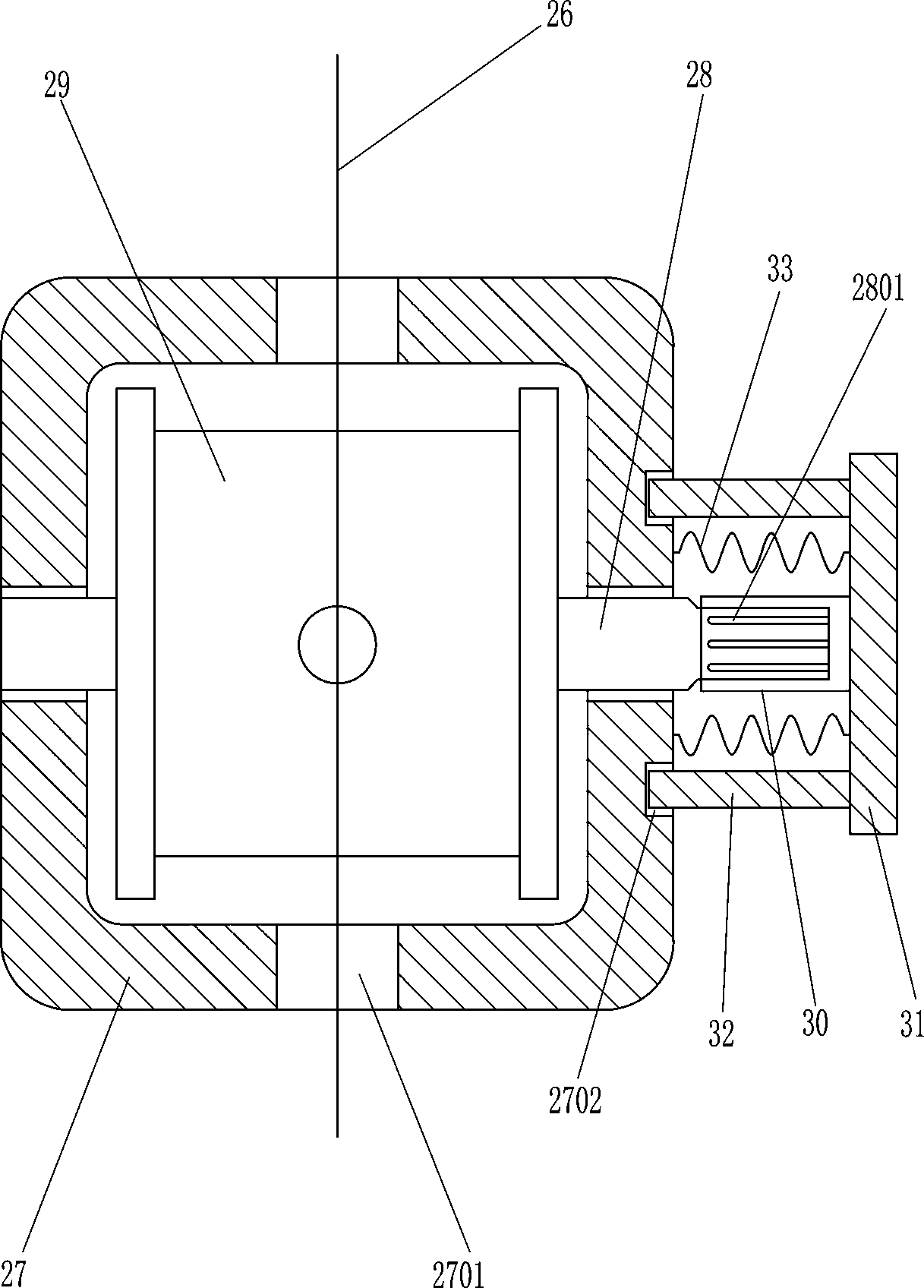
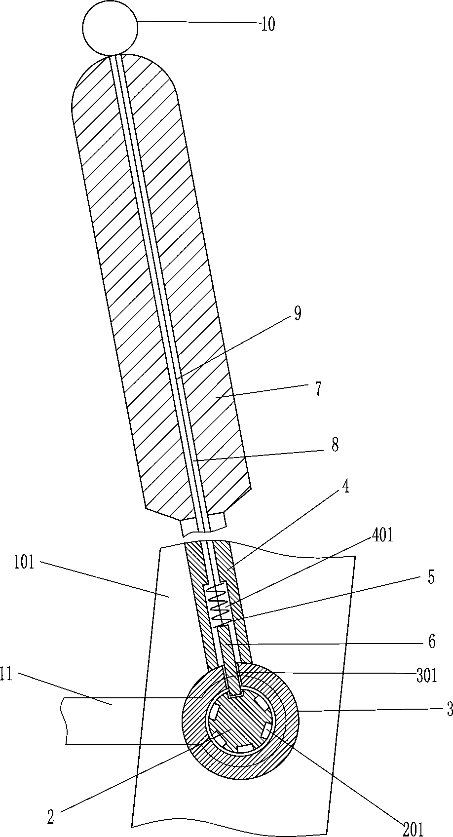
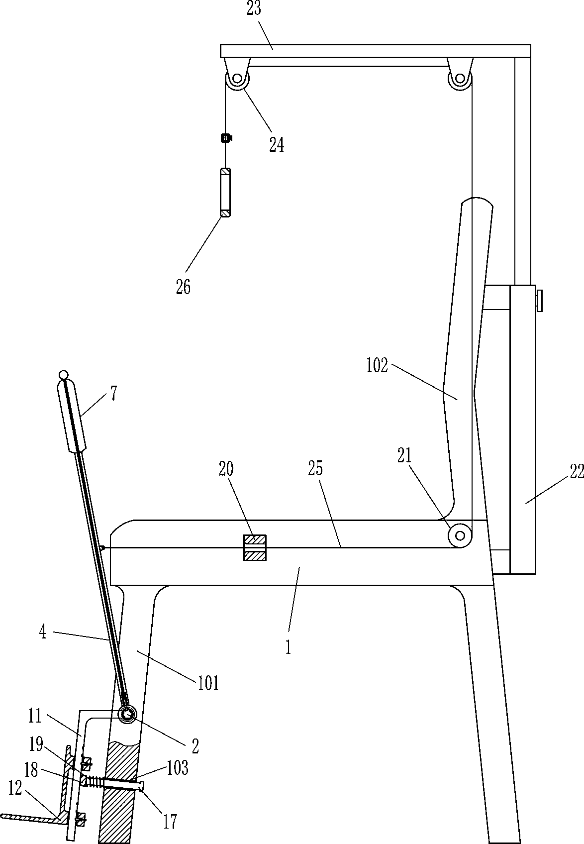
[0020] A medical leg rehabilitation chair, such as Figure 1-4As shown, it includes a seat base 1, chair legs 101, a chair back 102, a first rotating shaft 2, a rotating sleeve 3, a hollow steel tube 4, a first spring 5, a first pin rod 6, a handle 7, and a first pull cord 9 , the first draw ring 10, the L-shaped support 11, the L-shaped foot plate 12, the second pin bar 13, the second spring 14, the second stay cord 15 and the second draw ring 16, the left and right sides of the seat 1 bottom are all Supporting chair legs 101 are installed, the right side of the seat 1 top is fixedly equipped with a chair back 102, and the first rotating shaft 2 is installed in the middle part of the front side of the left chair leg 101 in a rotational manner, on the peripheral wall of the first rotating shaft 2 A plurality of first grooves 201 for fixing are evenly spaced, and the rotary sleeve 3 is slidably sleeved on the first rotating shaft 2, and the second through hole 301 for guiding i...

Embodiment 2

[0022] A medical leg rehabilitation chair, such as Figure 1-4 As shown, it includes a seat base 1, chair legs 101, a chair back 102, a first rotating shaft 2, a rotating sleeve 3, a hollow steel tube 4, a first spring 5, a first pin rod 6, a handle 7, and a first pull cord 9 , the first draw ring 10, the L-shaped support 11, the L-shaped foot plate 12, the second pin bar 13, the second spring 14, the second stay cord 15 and the second draw ring 16, the left and right sides of the seat 1 bottom are all Supporting chair legs 101 are installed, the right side of the seat 1 top is fixedly equipped with a chair back 102, and the first rotating shaft 2 is installed in the middle part of the front side of the left chair leg 101 in a rotational manner, on the peripheral wall of the first rotating shaft 2 A plurality of first grooves 201 for fixing are evenly spaced, and the rotary sleeve 3 is slidably sleeved on the first rotating shaft 2, and the second through hole 301 for guiding ...

Embodiment 3

[0025] A medical leg rehabilitation chair, such as Figure 1-4 As shown, it includes a seat base 1, chair legs 101, a chair back 102, a first rotating shaft 2, a rotating sleeve 3, a hollow steel tube 4, a first spring 5, a first pin rod 6, a handle 7, and a first pull cord 9 , the first draw ring 10, the L-shaped support 11, the L-shaped foot plate 12, the second pin bar 13, the second spring 14, the second stay cord 15 and the second draw ring 16, the left and right sides of the seat 1 bottom are all Supporting chair legs 101 are installed, the right side of the seat 1 top is fixedly equipped with a chair back 102, and the first rotating shaft 2 is installed in the middle part of the front side of the left chair leg 101 in a rotational manner, on the peripheral wall of the first rotating shaft 2 A plurality of first grooves 201 for fixing are evenly spaced, and the rotary sleeve 3 is slidably sleeved on the first rotating shaft 2, and the second through hole 301 for guiding ...


PUM


Abstract

The invention relates to a medical rehabilitation chair, in particular to a medical leg rehabilitation chair. Thus, the medical leg rehabilitation leg aims at achieving the technical purposes that fatigue can be avoided, and the rehabilitation efficiency can be improved. According to the technical scheme, the medical rehabilitation chair comprises a chair seat, chair legs, a chair back, a first rotary shaft, a rotary sleeve, a hollow steel pipe, a first spring, a first pin rod, a handle, a first pull rope and the like. The chair legs with the supporting effect are mounted on the left side andthe right side of the bottom of the chair seat, the chair back is fixedly mounted on the right side of the top of the chair seat, and the first rotary shaft is rotationally mounted in the middle of the front side face of the chair leg on the left side. Through up-and-down swing of an L-shaped support, the legs of a patient can swing up and down, thus, the legs of the patient can be subjected to rehabilitation training, then medical staff do not need to exercise the legs of the patient by hand, and therefore physical fatigue of the medical staff can be avoided; a buffer rod, a buffer cushion and a third spring achieve a buffer effect, and therefore secondary harm to the legs of the patient can be avoided.

Description

technical field [0001] The invention relates to a medical rehabilitation chair, in particular to a medical leg rehabilitation chair. Background technique [0002] In order to make the patient's legs recover quickly, it is necessary to exercise the patient's legs. At present, when exercising the patient's legs, the medical staff usually bend the patient's legs, but this method takes a long time and is easy. It makes the medical staff physically tired, and it is difficult for the medical staff to use appropriate strength to bend the legs according to the patient's condition. In order to prevent the physical fatigue of the medical staff, the medical staff will reduce the time for bending the patient's legs, which will increase the patient's Time for leg recovery. Contents of the invention [0003] In order to overcome the shortcoming that the medical staff bend the patient's legs for a long time and the body is prone to fatigue, and it is difficult for the medical staff to u...

Claims


Application Information

Patent Timeline
IPC IPC(8): A61H1/02A63B23/12
CPCA61H1/0237A61H2201/0149A61H2201/1269A61H2201/164A61H2205/10A63B23/12A63B2210/02
Inventor 唐钦弘
Owner 湖北医药学院附属随州医院
Why Eureka
Try Eureka