Blood plasma separation micro passage and separation chip

A plasma separation and separation channel technology, applied in the field of plasma separation, can solve the problems of small amount of plasma, blockage of filter pores, and low plasma yield, etc.

Inactive Publication Date: 2019-04-16
杨雁婷 +1
View PDF3 Cites 0 Cited by
  • Summary
  • Abstract
  • Description
  • Claims
  • Application Information

AI Technical Summary

Problems solved by technology

For example, the plasma separation method based on membrane osmosis, the plasma obtained by this method is often small, and needs to be adsorbed in the membrane or on the surface, the filter pores are easily blocked, and the practical application range is very limited.
The microfluidic plasma separation method based on cross-flow filtration can reduce the possibility of pore blockage, but the plasma yield is low

Method used


Image

  • Blood plasma separation micro passage and separation chip
  • Blood plasma separation micro passage and separation chip
  • Blood plasma separation micro passage and separation chip

Examples


Embodiment 1

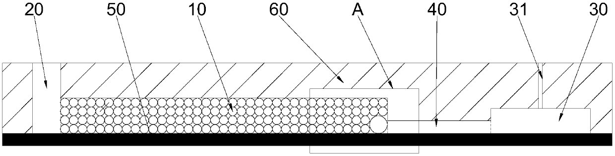
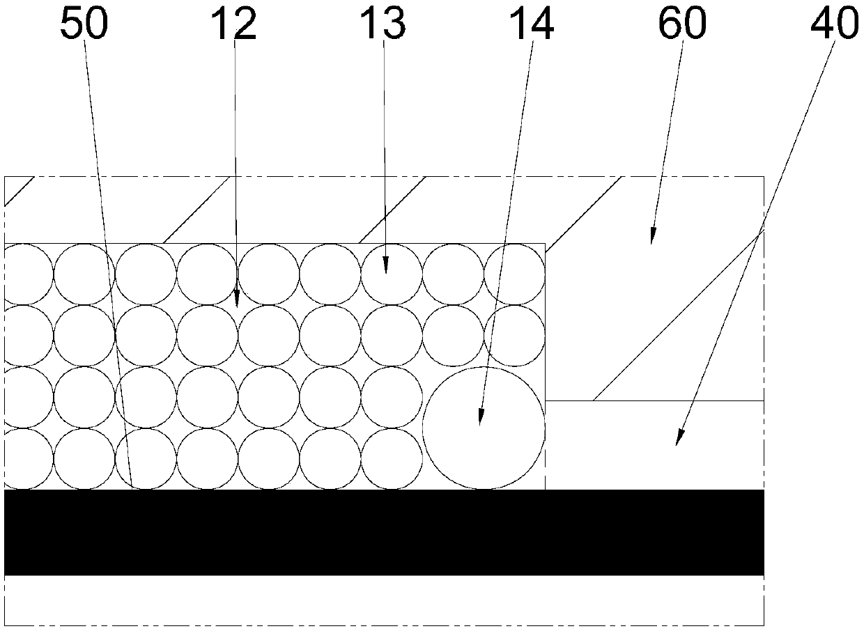
[0029] Such as figure 1 Shown is a schematic structural diagram of Embodiment 1 of the plasma separation chip of the present invention. The plasma separation chip of this embodiment includes the above plasma separation microchannel 10 . The plasma separation microchannel 10 of this embodiment includes accommodating cavities 11 for accommodating red blood cells. The accommodating cavities 11 are distributed in a spatial array, and there is a barrier between two adjacent accommodating cavities 11 that can be used for red blood cells to pass through while simultaneously treating red blood cells. The communication channel 12 where the flow acts as a barrier. One end of the plasma separation microchannel 10 is provided with a blood sampling chamber 20 , and the other end is provided with a collection chamber 30 for collecting plasma. The collection chamber 30 is provided with an air outlet 31 . A separation channel 40 for circulating the separated plasma is provided between the p...

Embodiment 2

[0034] Such as Image 6 Shown is a schematic structural view of Embodiment 2 of the plasma separation chip of the present invention. The plasma separation chip of this embodiment includes the above plasma separation microchannel 10 . The plasma separation microchannel 10 of this embodiment includes accommodating cavities 11 for accommodating red blood cells. The accommodating cavities 11 are distributed in a spatial array, and there is a barrier between two adjacent accommodating cavities 11 that can be used for red blood cells to pass through while simultaneously treating red blood cells. The communication channel 12 where the flow acts as a barrier. One end of the plasma separation microchannel 10 is provided with a blood sampling chamber 20 , and the other end is provided with a collection chamber 30 for collecting plasma. The collection chamber 30 is provided with an air outlet 31 . A separation channel 40 for circulating the separated plasma is provided between the plas...


PUM


Abstract

The invention discloses a blood plasma separation micro passage. The passage comprises accommodating cavities used for accommodating erythrocytes, the accommodating cavities are distributed in space array, and a communicating passage used for the erythrocytes to penetrate through and blocking flowing of the erythrocytes is arranged between every two adjacent accommodating cavities. The invention further discloses a blood plasma separation chip. The blood plasma separation chip comprises the above-mentioned blood plasma separation micro passage, a blood sample inlet cavity is formed at one endof the blood plasma separation micro passage, and a collecting cavity used for collecting blood plasma is formed at the other end of the blood plasma separation micro passage. The blood plasma separation micro passage and the separation chip thereof can directly separate blood plasma, can avoid blockage, and can be suitable for the field of instant blood detection and the like.

Description

technical field [0001] The invention belongs to the technical field of plasma separation, in particular to a plasma separation microchannel and a separation chip. Background technique [0002] Plasma separation is of great significance to clinical testing. In traditional laboratory analysis methods, the most common way to separate plasma is to centrifuge whole blood in a desktop centrifuge, and then extract the supernatant to obtain plasma. However, in blood point-of-care testing (POCT) equipment that is more and more widely used, the plasma preparation method based on centrifugation is difficult to meet the requirements due to the large device and high cost. [0003] The use of microfluidic technology for the separation of plasma from whole blood has therefore become a research hotspot at present, and a variety of different microfluidic devices have been used in plasma separation research. For example, the plasma separation method based on membrane osmosis usually obtains ...

Claims


Application Information

Patent Timeline
IPC IPC(8): B01L3/00G01N1/34
CPCB01L3/502761B01L2200/027B01L2200/0631B01L2200/10G01N1/34
Inventor 杨雁婷邓治杨
Owner 杨雁婷
Why Eureka
Try Eureka