Automatic welding system for robots

An automatic welding and robot technology, applied in welding equipment, auxiliary welding equipment, welding/cutting auxiliary equipment, etc., can solve the problems of cumbersome steps, poor versatility, long construction period for batch processing of workpieces, etc., to shorten the construction period and enhance the versatility. Effect

Active Publication Date: 2019-04-16
杭州固建机器人科技有限公司
View PDF8 Cites 16 Cited by
  • Summary
  • Abstract
  • Description
  • Claims
  • Application Information

AI Technical Summary

Problems solved by technology

[0004] 1. The position of the fixture on the material processing table is fixed, and a welding production line can only process a welding workpiece of a specific standard, which has poor versatility;
[0005] 2. The above steps are relatively cumbersome and during the batch p

Method used


Image

  • Automatic welding system for robots
  • Automatic welding system for robots
  • Automatic welding system for robots

Examples


Embodiment Construction

[0032] The preferred embodiments of this patent will be described in further detail below in conjunction with the accompanying drawings.

[0033] In this application, for the convenience of description, the direction parallel to the sliding direction of the overturn support mechanism is called the length direction, and the direction perpendicular to the sliding direction of the overturn support mechanism is called the width direction.

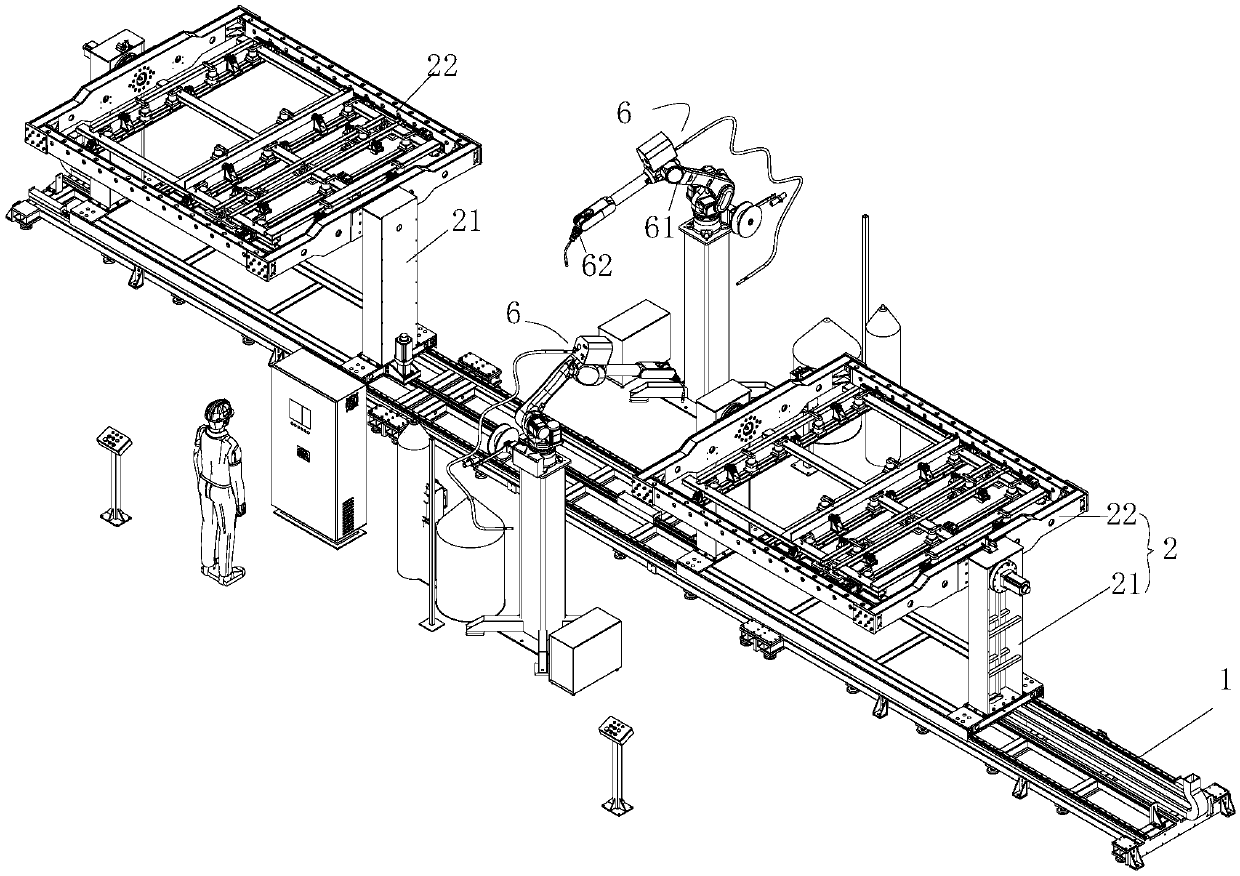
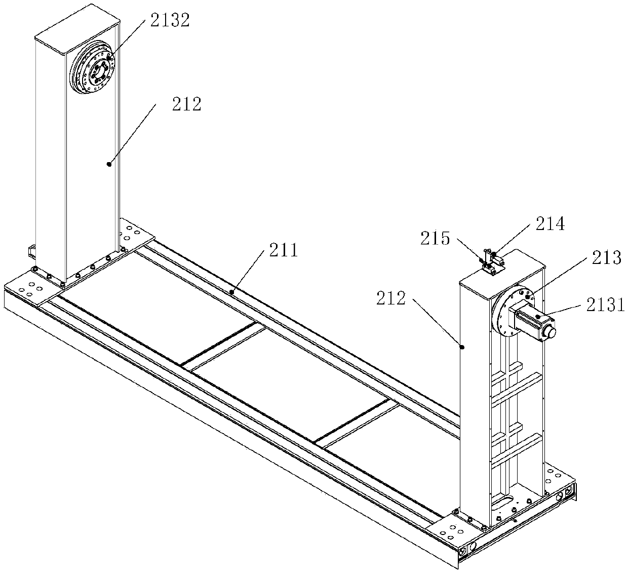
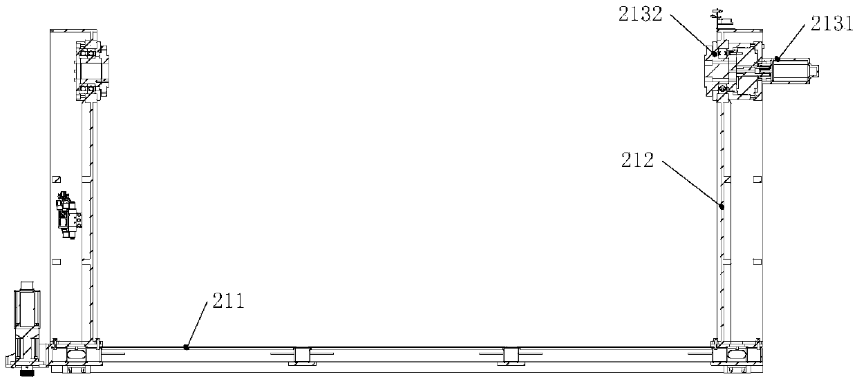
[0034] Such as figure 1The shown automatic welding system for robots includes a conveying track along which a feeding station, a welding station and a feeding station are sequentially arranged. A welding mechanism is provided on both sides of the welding station, and the welding mechanism includes a rotating arm with multiple degrees of freedom and a welding head mounted on the rotating arm. Two or more overturning support mechanisms 2 are slidably installed on the conveying track 1, and a driving device is provided on the conveying track 1, a...


PUM


Abstract

The invention relates to an automatic welding system for robots. The system comprises a conveying rail; a loading station, a welding station and an unloading station are arranged along the conveying rail in sequence; overturning support mechanisms are slidingly mounted on the conveying rail; a driving device is arranged on the conveying rail, and drives the overturning support mechanisms to move to different stations along the conveying rail; the overturning support mechanisms comprise brackets, and flexible clamping assemblies rotationally mounted on the brackets; and the flexible clamping assemblies comprise frames, multiple cross beams slidingly arranged on the frames, and multiple fixtures for clamping profiles to be welded. Two or more overturning support mechanisms capable of movingto different stations along the conveying rail are provided; and the two overturning support mechanisms can synchronously perform different procedures, so that the large-batch machining efficiency ofworkpieces can be improved.

Description

technical field [0001] The invention relates to automatic welding equipment, in particular to an automatic welding system for robots. Background technique [0002] For the welding of the plane frame, it is necessary to weld and fix both the front and back sides of the joints of multiple profiles. In the prior art, the welding of the plane frame is generally divided into the following steps according to the production process: 1. Loading, loading multiple profiles onto the operating platform, and assembling the multiple profiles into the prototype of the plane frame for preliminary fixing ; 2. Weld and fix all the welding points on one side of the assembled plane frame; 3. Turn over the plane frame after one side has been welded and perform the next step of welding; 4. Cut the material. [0003] In the above process, the above steps are generally manually operated, and manual operation has problems such as low efficiency and poor welding quality. In order to make up for the...

Claims


Application Information

Patent Timeline
IPC IPC(8): B23K37/00B23K37/04B23K37/047B23K37/02
CPCB23K37/00B23K37/0252B23K37/0435B23K37/047
Inventor 邱甜刘泽裕胡国强
Owner 杭州固建机器人科技有限公司
Why Eureka
Try Eureka