Linear sliding assembly

A linear sliding and assembly technology, used in auxiliary devices, supporting machines, auxiliary welding equipment, etc., can solve the problems of increasing sliding friction, short service life, and easy damage, avoiding accumulation, improving sliding stability, extending The effect of service life

Inactive Publication Date: 2019-04-16
重庆伊莱卡实业有限公司
View PDF0 Cites 1 Cited by
  • Summary
  • Abstract
  • Description
  • Claims
  • Application Information

AI Technical Summary

Problems solved by technology

[0002] When cutting the material, the cutting material cut with the assistance of the cutting device is relatively flat. The automatic cutting device usually used is to install the cutting gun on the sliding sleeve, and then put the sliding sleeve on the sliding rod to move the cutting gun. The sliding sleeve in the cutting device with this structure is easy to enter the cutting waste, which will increase the sliding friction, and it is easy to damage and the service life is short

Method used


Image

  • Linear sliding assembly
  • Linear sliding assembly

Examples


Embodiment

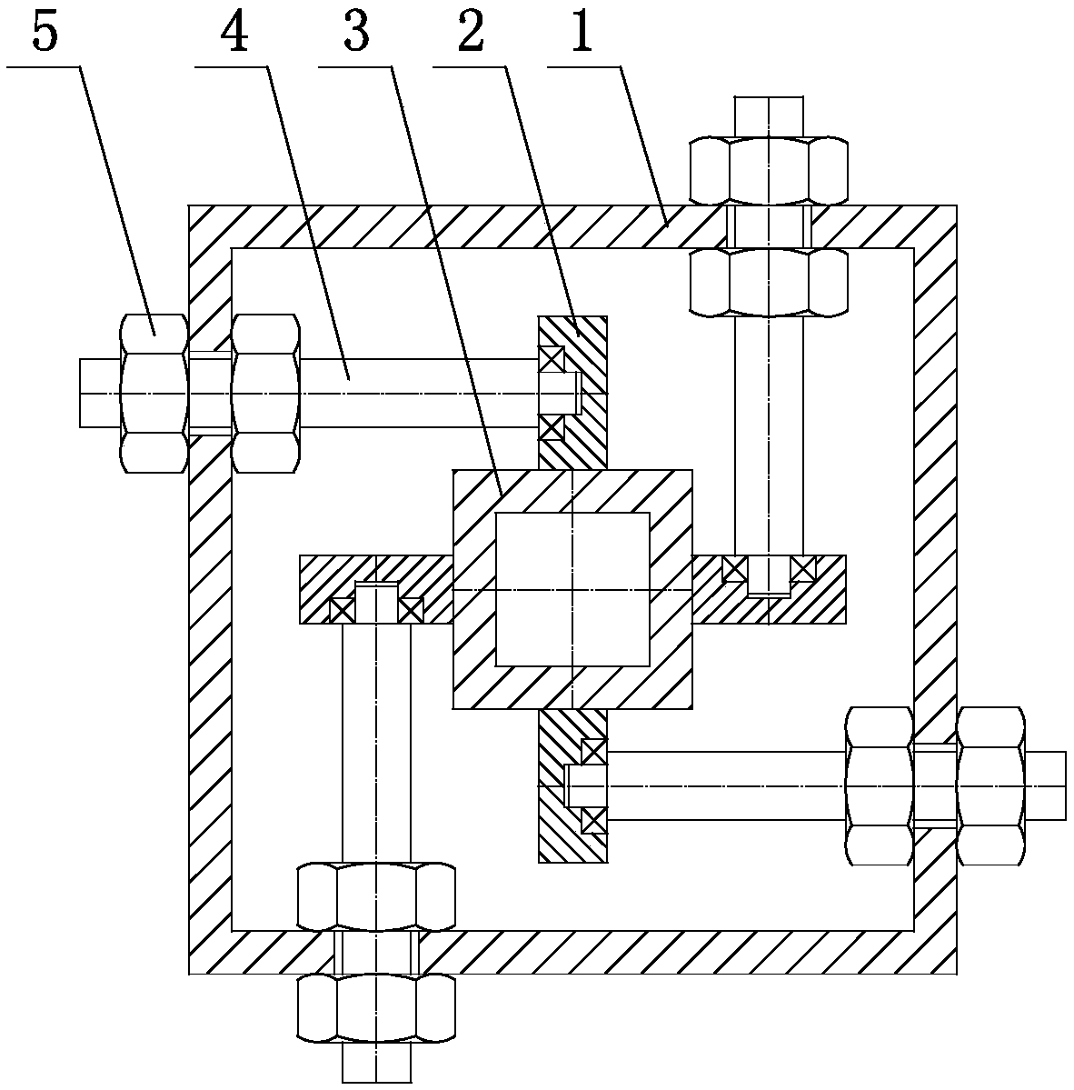
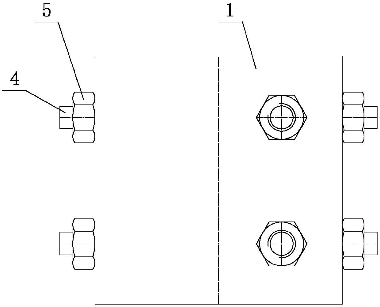
[0019] like figure 1 , figure 2 As shown, the linear sliding assembly includes an outer square tube 1 arranged horizontally, an inner square tube 3 is installed horizontally inside the outer square tube 1, and an inner square tube 3 is installed on the upper, lower, left and right sides of the inner square tube 3. Positioning shafts 4, each positioning shaft 4 is mounted on the outer tube, each positioning shaft 4 is provided with a rotating roller 2, and each rotating roller 2 is distributed on the upper surface, bottom, left side of the inner square tube 3 On the side and the right side, each positioning shaft 4 is provided with threads, and each positioning shaft 4 is installed on the outer tube 1 through a nut 5 .

[0020] In this embodiment, each rotating roller 2 is mounted on the positioning shaft 4 through a bearing. The technical design of this section improves the flexibility of the rotary roller 2 and prevents waste residues from entering the bearings in the rota...


PUM


Abstract

The invention relates to a linear sliding assembly, and belongs to the technical field of linear sliding assemblies. The linear sliding assembly comprises an outer square tube horizontally arranged, an inner square tube is horizontally arranged in the outer square tube in a penetrating mode, and positioning shafts are arranged on the upper side, lower side, left side and right side of the inner square tube, each positioning shaft is arranged on the outer square tube in a penetrating mode, and a rotating roller is arranged on each positioning shaft, and rotating rollers are distributed on the upper surface, bottom part, the left side surface and the right side surface of the inner square tube, threads are arranged on each positioning shaft, and each positioning shaft is installed on the outer square tube through nuts. According to the linear sliding assembly, the accumulation of the cutting waste residue can be avoided, the sliding stability of the device is improved, and the service life of the device is prolonged.

Description

technical field [0001] The invention relates to a linear sliding assembly, which belongs to the technical field of linear sliding assemblies. Background technique [0002] When cutting the material, the cutting material cut with the assistance of the cutting device is relatively flat. The automatic cutting device usually used is to install the cutting gun on the sliding sleeve, and then put the sliding sleeve on the sliding rod to move the cutting gun. The sliding sleeve in the cutting device of this structure is easy to enter the cutting waste, which will increase the sliding friction, and is easy to damage and has a short service life. Contents of the invention [0003] Based on the above deficiencies in the prior art, the technical problem to be solved by the present invention is to provide a linear sliding assembly, which is convenient to use in harsh environments, improves the sliding stability of the device, and prolongs the service life of the equipment. [0004] T...

Claims


Application Information

Patent Timeline
Patent Type & Authority Applications(China)
IPC IPC(8): B23K37/02F16M11/02F16M11/04
CPCB23K37/02B23K37/0211F16M11/02F16M11/04
Inventor 刘斌
Owner 重庆伊莱卡实业有限公司
Why Eureka
Try Eureka