Electrorheological fluid clamping tool for light and low-noise gearbox

An electrorheological fluid, clamping tooling technology, applied in clamping, positioning devices, manufacturing tools, etc., can solve the problems of low production efficiency, prolonging the finishing time of the gearbox, and the gearbox being dropped and damaged. The force is uniform and firm, the workpiece clamping effect is good, and the effect of fast loading and unloading of workpieces

Active Publication Date: 2019-04-16
江阴市惠尔信精密装备股份有限公司
View PDF5 Cites 46 Cited by
  • Summary
  • Abstract
  • Description
  • Claims
  • Application Information

AI Technical Summary

Problems solved by technology

The gear box needs to bear the external force exerted by the milling cutter, drill bit and other processing equipment during the finishing process. If the clamping tooling strength of the clamping gear box is not appropriate, or the structure of the clamping tooling is unreasonable, the gear box may shift or fall off , resulting in the offset of the finishing position or the drop and damage of the gearbox, resulting in waste products; in addition, most of the existing clamping tools for the finishing of the gearbox can only process one side of the gearbox, and the other side of the gearbox needs to be processed. The gear box is removed from the tooling and re-fixed to the clamping tool after turning 180°, which prolongs the man-hours of finishing the gear box and leads to low production efficiency

Method used


Image

  • Electrorheological fluid clamping tool for light and low-noise gearbox
  • Electrorheological fluid clamping tool for light and low-noise gearbox
  • Electrorheological fluid clamping tool for light and low-noise gearbox

Examples


Embodiment Construction

[0022] The specific implementation manners of the present invention will be further described below in conjunction with the drawings and examples. The following examples are only used to illustrate the technical solution of the present invention more clearly, but not to limit the protection scope of the present invention.

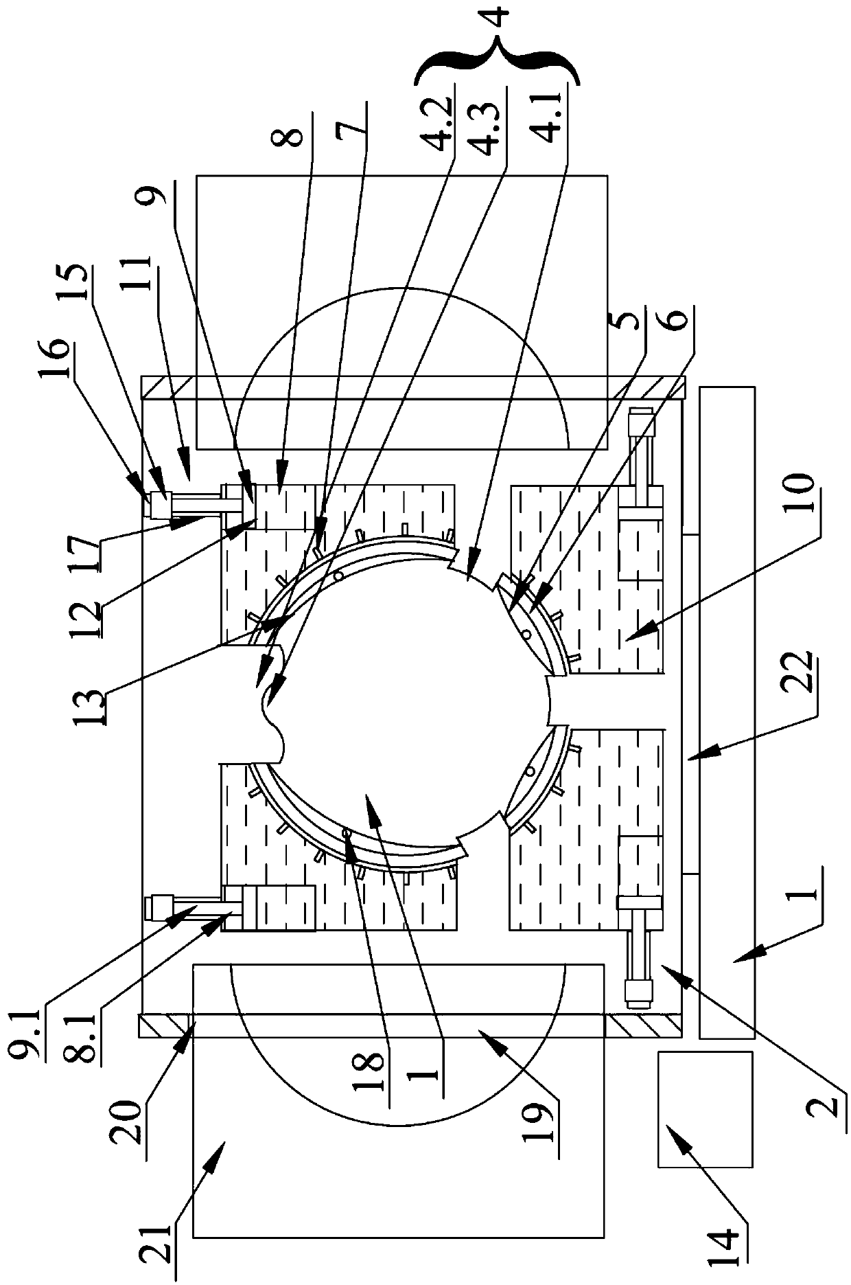
[0023] Such as Figure 1~2 As shown, the present invention is an electrorheological fluid clamping tool for a light-duty low-noise gearbox, which is used for positioning and clamping the end face of the gearbox during processing. The tool includes a base 1 on which a There is a workpiece carrying plate 2 perpendicular to the base 1, the middle part of the workpiece carrying plate 2 is provided with a through hole 3 for loading and unloading the workpiece, the inner wall of the through hole 3 is provided with a protruding positioning block 4, and the passage between the positioning blocks 4 The inner wall of the hole 3 is provided with a flexible liquid bag...


PUM


Abstract

The invention discloses an electrorheological fluid clamping tool for a light and low-noise gearbox. The electrorheological fluid clamping tool is used for positioning and clamping the end face of thegearbox in the machining process, the tool comprises a base, the base is provided with a workpiece bearing plate perpendicular to the base, a through hole used for mounting and demounting the workpiece is formed in the middle of the workpiece bearing plate, protruding positioning blocks are arranged on the inner wall of the through hole, flexible fluid bag storing grooves are formed in the positions, between the positioning blocks, of the inner wall of the through hole, flexible fluid bags are arranged in the storing grooves and connected with a cylinder body through guiding pipes, the cylinder body is internally provided with a piston, the space, at one end of the piston, inside the cylinder body, the guiding pipes and the flexible fluid bags constitute an accommodating chamber for electrorheological fluid jointly, the other end of the piston is connected with a piston driving mechanism, positive electrodes and negative electrodes are arranged at one end of the piston and the inner walls of the flexible fluid bags correspondingly, and the positive electrodes and the negative electrodes are connected with a controller. The electrorheological fluid clamping tool is simple in structure, convenient to use and good in workpiece clamping effect, clamping force in all directions of the workpiece is uniform and firm, and the workpiece can be quickly mounted and demounted.

Description

technical field [0001] The invention relates to the technical field of machining and manufacturing tooling for mechanical products, in particular to an electrorheological fluid clamping tool for a light-duty low-noise gearbox. Background technique [0002] Gearbox is an important part in mechanical transmission, and its precision directly affects the efficiency of mechanical operation. The gear box needs to bear the external force exerted by the milling cutter, drill bit and other processing equipment during the finishing process. If the clamping tooling strength of the clamping gear box is not appropriate, or the structure of the clamping tooling is unreasonable, the gear box may shift or fall off , resulting in the offset of the finishing position or the drop and damage of the gearbox, resulting in waste products; in addition, most of the existing clamping tools for the finishing of the gearbox can only process one side of the gearbox, and the other side of the gearbox nee...

Claims


Application Information

Patent Timeline
Patent Type & Authority Applications(China)
IPC IPC(8): B23Q3/08
CPCB23Q3/08B23Q3/082
Inventor 徐惠民罗旭王杰
Owner 江阴市惠尔信精密装备股份有限公司
Why Eureka
Try Eureka