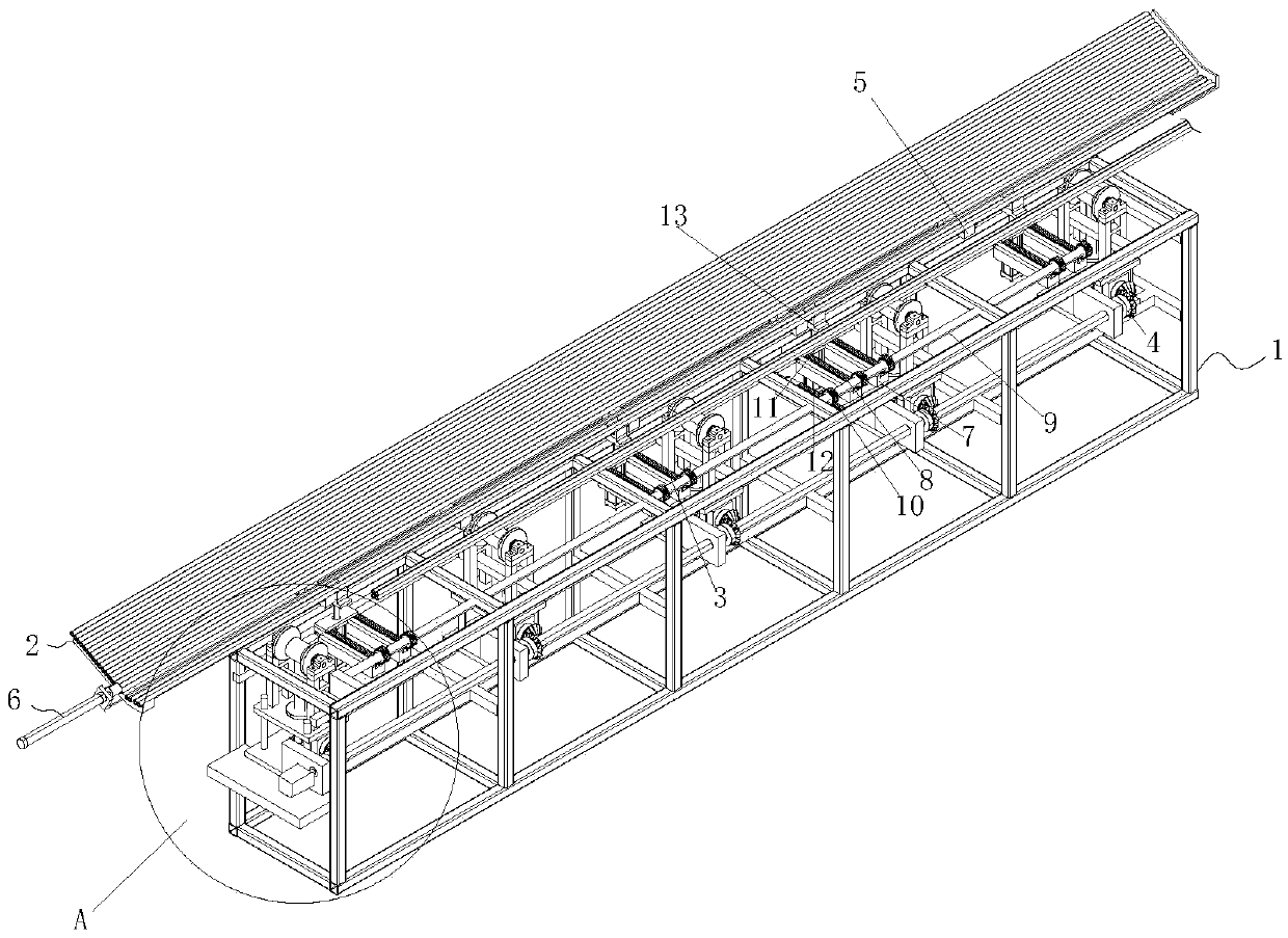
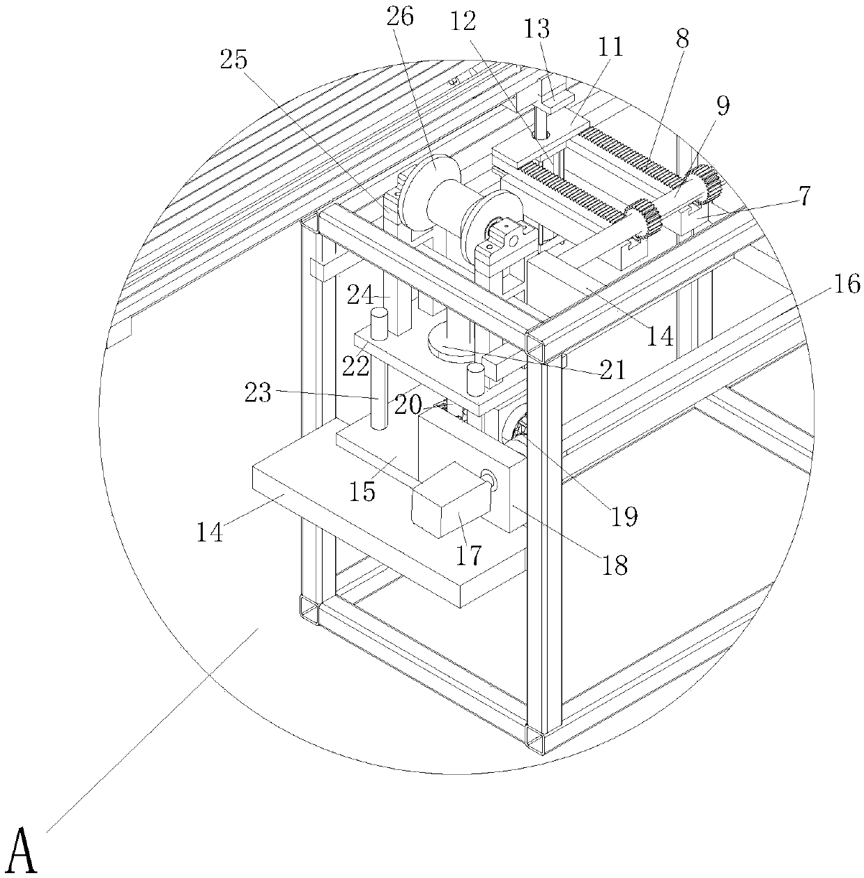
Feeding device of steel pipe cutting machine

A cutting machine and steel pipe technology, applied in shearing machine equipment, metal processing equipment, pipe cutting devices, etc., can solve the problems of inability to feed steel pipes, poor versatility, time-consuming and labor-intensive, etc.

Inactive Publication Date: 2019-04-16
TIANJIN JUXINGXIANGHAI MACHINERY CO LTD
View PDF6 Cites 2 Cited by
  • Summary
  • Abstract
  • Description
  • Claims
  • Application Information

AI Technical Summary

Problems solved by technology

Manual feeding requires a lot of manpower to send steel pipes into the cutting machine. This method is labor-intensive, time-consuming and labor-intensive, and has low efficiency; although mechanical feeding solves the low efficiency caused by manual labor, it is time-consuming There is poor versatility, and it cannot be loaded according to steel pipes of different sizes, resulting in long working cycles and low working efficiency

Method used


Image

  • Feeding device of steel pipe cutting machine
  • Feeding device of steel pipe cutting machine

Examples


Embodiment Construction

[0013] It should be noted that, in the case of no conflict, the embodiments of the present invention and the features in the embodiments can be combined with each other.

[0014] In describing the present invention, it should be understood that the terms "center", "longitudinal", "transverse", "upper", "lower", "front", "rear", "left", "right", " The orientations or positional relationships indicated by "vertical", "horizontal", "top", "bottom", "inner" and "outer" are based on the orientations or positional relationships shown in the drawings, and are only for the convenience of describing the present invention and Simplified descriptions, rather than indicating or implying that the device or element referred to must have a particular orientation, be constructed and operate in a particular orientation, and thus should not be construed as limiting the invention. In addition, the terms "first", "second", etc. are used for descriptive purposes only, and should not be understood ...


PUM

PropertyMeasurementUnit
diameteraaaaaaaaaa
diameteraaaaaaaaaa

Abstract

The invention relates to a feeding device of a steel pipe cutting machine. The feeding device of the steel pipe cutting machine comprises a feeding frame. A storage unit, a pipe transferring unit anda pipe conveying unit are arranged on the feeding frame. The storage unit is fixedly connected to the feeding frame, and the pipe conveying unit is arranged on the outer side of the storage unit. Thepipe transferring unit is located between the storage unit and the pipe conveying unit and is used for transferring steel pipes on the storage unit to the pipe conveying unit. The pipe transferring unit comprises a first rack support, a first rack, a pipe transferring base plate, a first gear shaft and a pipe transferring support. The pipe conveying unit comprises a pipe conveying base plate, a pipe conveying supporting plate, a pipe conveying positioning plate, a second gear shaft and a lead screw. The lead screw is connected with the first gear shaft through a bevel gear. A sliding sleeve isarranged on the lead screw. A connecting plate is fixedly connected to the sliding sleeve. Two supporting rods are arranged on the connecting plate. Roller bases are fixedly connected to the upper ends of the supporting rods. Pipe conveying rollers are arranged on the roller bases. The feeding device of the steel pipe cutting machine is good in universality and high in efficiency.

Description

technical field [0001] The invention belongs to the field of steel pipe cutting auxiliary equipment, in particular to a feeding equipment for a steel pipe cutting machine. Background technique [0002] A steel pipe made of a single piece of metal with no seams on the surface is called a seamless steel pipe. According to the production method, seamless pipes are divided into hot-rolled pipes, cold-rolled pipes, cold-drawn pipes, extruded pipes, and jacking pipes. According to the cross-sectional shape, seamless steel tubes are divided into two types: round and special-shaped, and special-shaped tubes have various complex shapes such as square, oval, triangular, hexagonal, melon-shaped, star-shaped, and finned tubes. The maximum diameter is 650mm, and the minimum diameter is 0.3mm. Depending on the application, there are thick-walled tubes and thin-walled tubes. Seamless steel pipes are mainly used as petroleum geological drilling pipes, cracking pipes for petrochemical ind...

Claims


Application Information

Patent Timeline
Patent Type & Authority Applications(China)
IPC IPC(8): B23Q7/00B23Q7/05B23D21/00
CPCB23D21/00B23Q7/00B23Q7/055
Inventor 崔振祥
Owner TIANJIN JUXINGXIANGHAI MACHINERY CO LTD
Why Eureka
Try Eureka