Eureka AIR delivers breakthrough ideas for toughest innovation challenges, trusted by R&D personnel around the world.

Low energy consumption and self-feeding transformer processing device for new energy automobile

A new energy vehicle and processing device technology, applied to presses, manufacturing tools, etc., can solve problems such as increasing energy consumption, affecting processing efficiency, and increasing production costs, so as to improve work efficiency, reduce energy consumption, and avoid local deformation Effect

Inactive Publication Date: 2019-04-16
合肥森隆环保科技有限公司
View PDF6 Cites 3 Cited by
  • Summary
  • Abstract
  • Description
  • Claims
  • Application Information

AI Technical Summary

Problems solved by technology

[0002] During the production and processing of the transformer, the parts of its components need to be processed separately with different processing equipment. For example, the shell or some insulating parts need to be profiling processed. However, after the existing profiling process is completed, it needs Manually or corresponding auxiliary equipment takes the workpiece out of the cavity and transfers it out of the processing equipment, which not only increases the production cost, but also affects the efficiency of processing, and if the auxiliary equipment is used to extract materials, additional energy consumption will be increased

Method used


Image

  • Low energy consumption and self-feeding transformer processing device for new energy automobile

Examples


Embodiment Construction

[0015] Below, the technical solution of the present invention will be described in detail through specific examples.

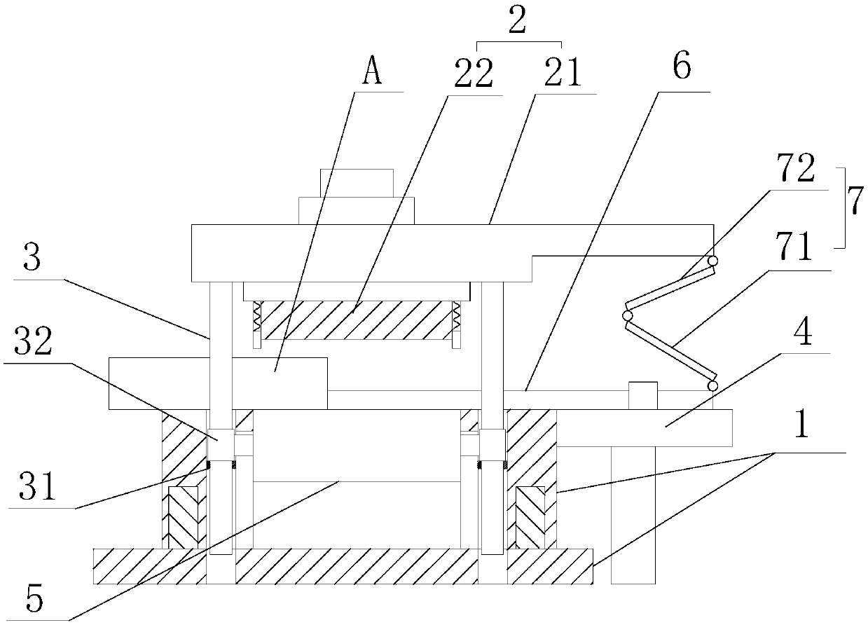
[0016] Such as figure 1 as shown, figure 1 It is a structural schematic diagram of a low-energy self-cutting transformer processing device for new energy vehicles proposed by the present invention.

[0017] refer to figure 1 , a low-energy self-cutting transformer processing device for new energy vehicles proposed in the embodiment of the present invention, comprising: a lower die 1, an upper die 2 located above the lower die 1, and a device for driving the upper die 2 to move up and down Drive mechanism, and pull rod 3 and guiding platform 4, wherein:

[0018] The lower die 1 is provided with a cavity and guide holes located outside the cavity. A bottom plate 5 that can slide up and down is arranged in the cavity, and the side wall of the bottom plate 5 is provided with a connecting portion, and the connecting portion is located in the chute. The depth o...


PUM


Abstract

The invention discloses a low energy consumption and self-feeding transformer processing device for a new energy automobile. The low energy consumption and self-feeding transformer processing device comprises a lower die, an upper die, a driving mechanism for driving the upper die to move up and down, a pulling rod and a guiding platform, wherein a cavity and a guiding hole are formed in the lowerdie, and a bottom plate is arranged in the cavity; the upper die comprises an upper die plate and a pressing block installed on the upper die plate; one end of the pulling rod and the upper die plateare fixed, and the other end of the pulling rod is located in the guiding hole; a limiting block and a sliding block are arranged on the pulling rod, and the sliding block is located between the limiting block and the upper die and connected with the bottom plate; a limiting hole and a pushing rod are arranged on the guiding platform, one end of the pushing rod penetrates through the limiting hole and is in sliding fit with the limiting hole, and the end, away from the cavity, of the pushing rod is connected with the side edge of the upper die and moves towards the cavity direction along withrising of the upper die and away from the cavity direction along with descending of the upper die. According to the low energy consumption and self-feeding transformer processing device for the new energy automobile, the actions of jacking and feeding of workpieces can be completed without additionally arrangement of a jacking mechanism and a feeding mechanism, energy consumption can be effectively lowered, and the working efficiency is improved.

Description

technical field [0001] The invention relates to the technical field of transformer processing equipment, in particular to a low-energy self-cutting transformer processing device for new energy vehicles. Background technique [0002] During the production and processing of the transformer, the parts of its components need to be processed separately with different processing equipment. For example, the shell or some insulating parts need to be profiling processed. However, after the existing profiling process is completed, it needs Manually or corresponding auxiliary equipment takes the workpiece out of the cavity and transfers it out of the processing equipment, which not only increases the production cost, affects the efficiency of processing, but also increases energy consumption if the auxiliary equipment is used to retrieve materials. Contents of the invention [0003] Based on the technical problems in the above-mentioned background technology, the present invention pr...

Claims


Application Information

Patent Timeline
Patent Type & Authority Applications(China)
IPC IPC(8): B30B9/28B30B15/02B30B15/32
CPCB30B9/28B30B15/02B30B15/026B30B15/32
Inventor 童星
Owner 合肥森隆环保科技有限公司
Why Eureka
Eureka Blog
Learn More