A gas turbine exhaust device

A technology for exhaust devices and gas turbines, applied in gas turbine devices, jet propulsion devices, mechanical equipment, etc., can solve the problems of unstable airflow, disordered flow direction, large total pressure loss, etc., and achieve high fault location accuracy and flow direction. Regular, stable effect of gas flow

Active Publication Date: 2022-03-04
AECC SHENYANG ENGINE RES INST
View PDF21 Cites 0 Cited by
  • Summary
  • Abstract
  • Description
  • Claims
  • Application Information

AI Technical Summary

Problems solved by technology

The existing round-to-square exhaust device adopts an integrated flow path structure, and its flow path has problems such as obvious gas flow separation, disordered flow direction, unstable air flow, and large total pressure loss, and it is difficult to disassemble and assemble the exhaust device. The accuracy of fault location is low, and the daily maintenance of the device is difficult

Method used


Image

  • A gas turbine exhaust device
  • A gas turbine exhaust device
  • A gas turbine exhaust device

Examples


Embodiment Construction

[0017] In order to make the purpose, technical solution and advantages of the application more clear, the technical solution in the embodiment of the application will be described in more detail below in conjunction with the drawings in the embodiment of the application.

[0018] The purpose of this application is to provide a gas turbine exhaust device, which can make the gas flow in the exhaust device more stable, the flow direction more regular, the total pressure loss smaller, and it has the advantages of simple disassembly and assembly, high accuracy of fault location and convenient maintenance function.

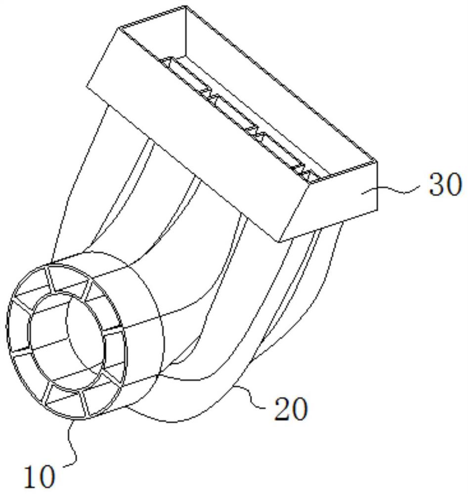
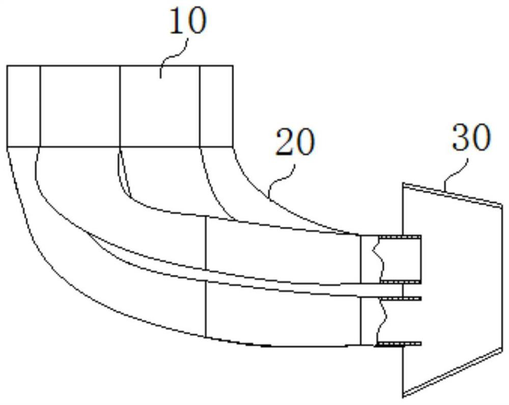
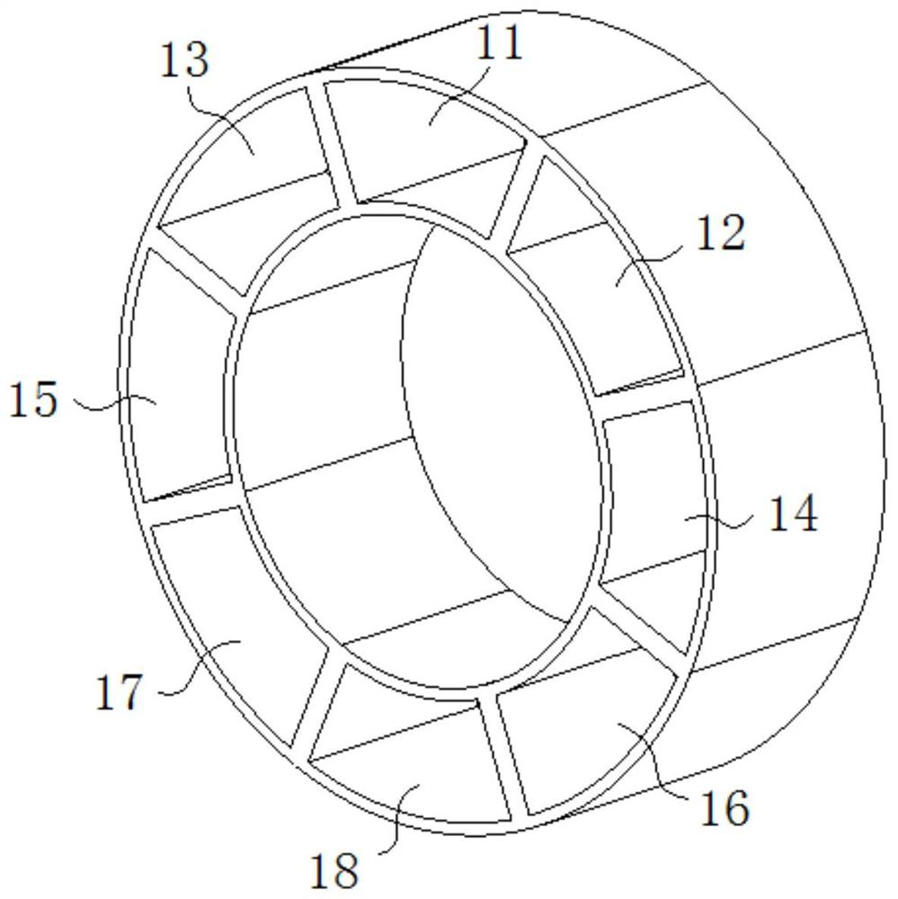
[0019] For this reason, the gas turbine exhaust device of the present application adopts a split flow path design, which includes a transition section 10 , a diffuser section 20 and a converging section 30 . The transition section 10 is a circular or annular structure, and the transition section 10 has 2 n A fan-shaped or fan-shaped air inlet passage, the diffuser sect...


PUM


Abstract

The application discloses a gas turbine exhaust device, which includes: a transition section, the transition section is a circular or ring-shaped structure, and the transition section has 2 n A fan-shaped or fan-shaped air intake channel; a diffuser section, the diffuser section is connected to the transition section, and the diffuser section has a diversion channel with the same number of intake channels, the inlet end and the outlet end of the diversion channel are perpendicular to each other, and turn to The passage has an inlet port and a rectangular outlet port having the same shape as the inlet passage; and a converging section, which is fixed to the outlet end of the diffuser section and is used for converging and diverting the passage into one body. The exhaust device of the gas turbine of the present application is designed in a split type through the flow path of the exhaust device, and the inlet gas is divided into 2 through the transition section. n Afterwards, through the deceleration and deflection of the diffuser section, the gas equivalent turning radius ratio is reduced, and finally converged into a flow path through the converging section, which also has the functions of ejection and rectification. This application makes the gas flow more stable and the flow direction more accurate. Regular, total pressure loss is smaller.

Description

technical field [0001] The application belongs to the technical field of gas turbine design, and in particular relates to a gas turbine exhaust device. Background technique [0002] In terms of the structure of the output shaft, the gas turbine exhaust device is divided into two types: the front shaft output type and the rear shaft output type. The structure of the front axle output type exhaust device is relatively simple, and the gas is deflected and discharged in a regular flow path; the rear axle output type has a more complicated internal flow path profile and structure because the output shaft must pass through the exhaust device. Restricted by the structure of the turbine rear casing, some rear output exhaust devices need to be designed with a circular inlet and a rectangular outlet. The existing round-to-square exhaust device adopts an integrated flow path structure, and its flow path has problems such as obvious separation of gas flow, disordered flow direction, un...

Claims


Application Information

Patent Timeline
Patent Type & Authority Patents(China)
IPC IPC(8): F01D25/30F02C7/00
CPCF01D25/30F02C7/00
Inventor 叶留增贾东兵巩亚南石岩
Owner AECC SHENYANG ENGINE RES INST
Why Eureka
Try Eureka