500/600KW-5000/6000 KW combined cold and heat supply device

A technology of combined cooling and heating and heat recovery pipes, which is applied in the direction of refrigerators, refrigeration components, refrigeration and liquefaction, etc., can solve problems such as inability to realize combined cooling and heating, small temperature adjustment range, single cooling or heating, etc., to achieve Simple structure, large temperature adjustment range, and the effect of improving energy efficiency ratio

Active Publication Date: 2019-04-16
安徽正刚新能源科技有限公司
View PDF7 Cites 1 Cited by
  • Summary
  • Abstract
  • Description
  • Claims
  • Application Information

AI Technical Summary

Problems solved by technology

[0005] What the present invention wants to overcome is that the current technology can only solve the problem of refrigeration or heating alone, and cannot realize the combined supply of cooling and heating at the same time, and the temperature adjustment range is small, and the adjustment accuracy is low. The purpose is to provide a 500 / 600KW-5000 / 6000KW combined cooling and heating device

Method used


Image

  • 500/600KW-5000/6000 KW combined cold and heat supply device
  • 500/600KW-5000/6000 KW combined cold and heat supply device
  • 500/600KW-5000/6000 KW combined cold and heat supply device

Examples


Embodiment 1

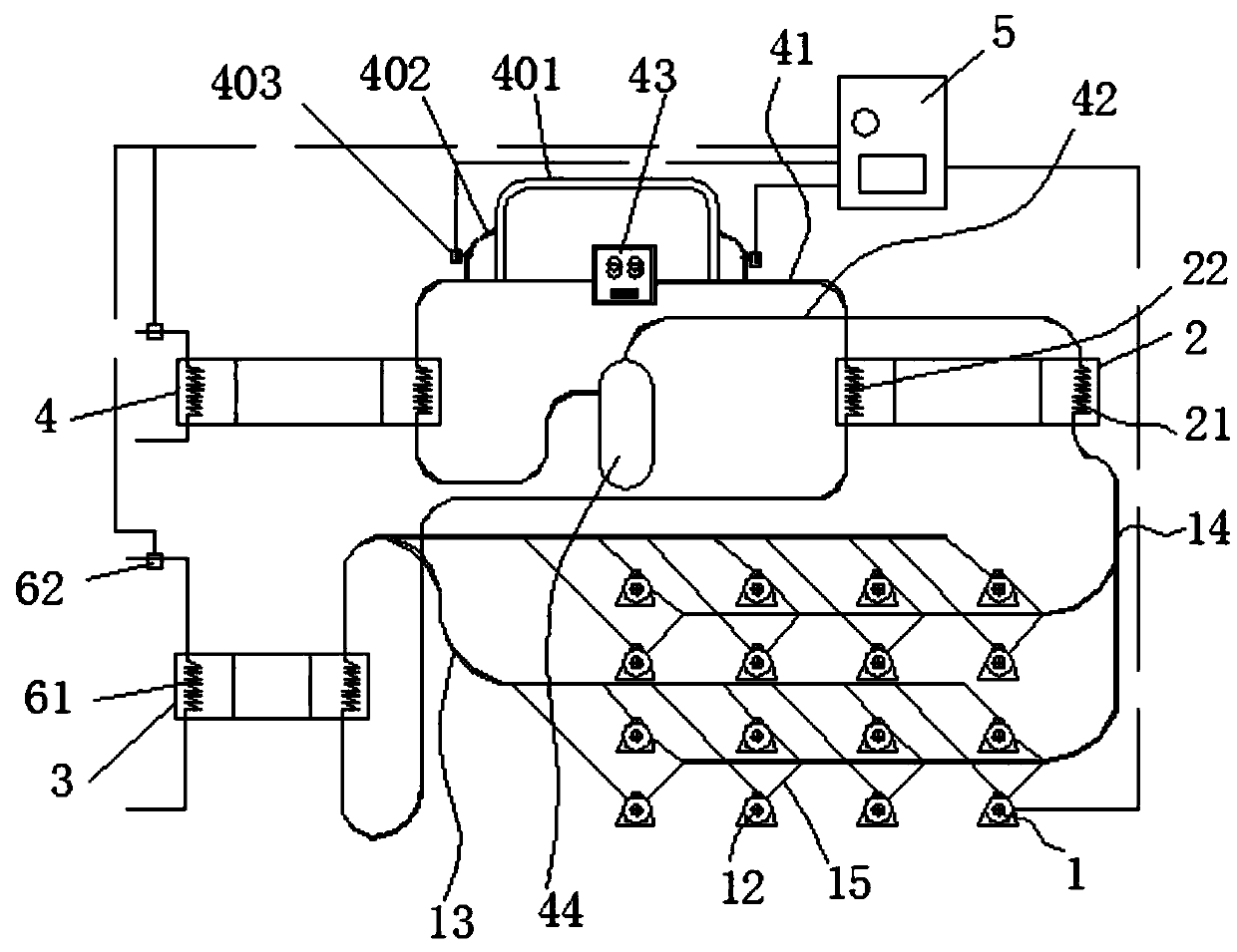
[0025] Such as figure 1 Shown; a 500 / 600KW-5000 / 6000KW combined cooling and heating device, including:

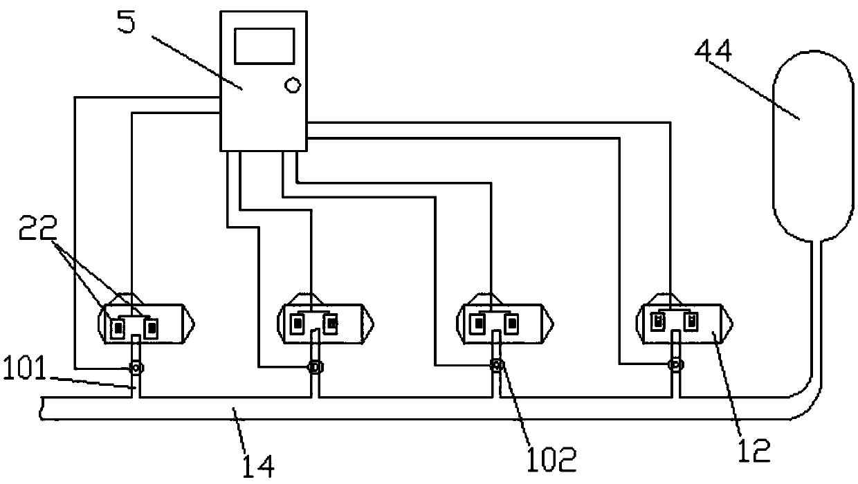
[0026] Compressor unit 1, at least eight groups of CO2 compressors 12 are connected in parallel in the compressor unit 1; a first pressure sensor is installed inside the main output pipeline 13 of the compressor unit 1, and a first pressure sensor is installed inside the main input pipeline 14 of the compressor unit 1 having a second pressure sensor;

[0027] The regenerator 2, the regenerator 2 includes a first heat recovery pipe 21 and a second heat recovery pipe 22, the end of the first heat recovery pipe 21 is connected to the main input pipe 14 of the compressor unit 1,

[0028] An air cooler 3, one end of which is connected to the main output pipeline 13 of the compressor unit 1; the other end of the air cooler 3 is connected to one end of the second heat return pipe 22 of the regenerator 2 through a pipe,

[0029] An evaporator 4, one end of the evaporator 4 is con...

Embodiment 2

[0071] Such as figure 1 Shown; a 500 / 600KW-5000 / 6000KW combined cooling and heating device, including:

[0072] Compressor unit 1, at least eight groups of CO2 compressors 12 are connected in parallel in the compressor unit 1; a first pressure sensor is installed inside the main output pipeline 13 of the compressor unit 1, and a first pressure sensor is installed inside the main input pipeline 14 of the compressor unit 1 having a second pressure sensor;

[0073] The regenerator 2, the regenerator 2 includes a first heat recovery pipe 21 and a second heat recovery pipe 22, the end of the first heat recovery pipe 21 is connected to the main input pipe 14 of the compressor unit 1,

[0074] An air cooler 3, one end of which is connected to the main output pipeline 13 of the compressor unit 1; the other end of the air cooler 3 is connected to one end of the second heat return pipe 22 of the regenerator 2 through a pipe,

[0075] An evaporator 4, one end of the evaporator 4 is con...


PUM


Abstract

The invention discloses a 500/600KW-5000/6000 KW combined cold and heat supply device. The 500/600KW-5000/6000 KW combined cold and heat supply device comprises a compressor unit, a regenerator, an air cooler, an evaporator and a DCS control cabinet, wherein at least eight groups of CO2 compressors are connected in parallel in the compressor unit; the regenerator comprises a first backheating pipeand a second backheating pipe, and the end socket of the first backheating pipe is connected to an input pipeline of the compressor unit; one end of the air cooler is connected to an output pipelineof the compressor unit, and the other end of the air cool is connected with one end of the second backheating pipe of the regenerator through a pipeline; one end of the evaporator is connected with the other end of the second backheating pipe of the regenerator through a backflow pipeline, and the other end of the evaporator is connected with the other end of the first backheating pipe of the regenerator through a connecting pipe; and the input end of the DCS control cabinet is separately and electrically connected with a first pressure sensor, a second sensor and the groups of compressors inthe compressor unit, and the control output end of the DCS control cabinet is separately connected with the groups of CO2 compressors in the compressor unit.

Description

technical field [0001] The invention relates to the field of energy equipment, in particular to a 500 / 600KW-5000 / 6000KW combined cooling and heating device. Background technique [0002] Current technology can only solve the unilateral problem of refrigeration or heating. Refrigeration equipment on the market, with freon as the refrigerant, cannot achieve rapid one-time large temperature difference cooling, and the cooling range is only 5 to 8 degrees. The equipment on the market that uses carbon dioxide as a refrigerant has a maximum power of less than 100KW and a low cooling capacity per unit time, which cannot meet large-scale cooling needs. [0003] For heating equipment on the market, Freon is used as the refrigerant, and the maximum heating temperature can only reach 55 degrees. The equipment on the market that uses carbon dioxide as a refrigerant has a maximum power of less than 100KW and a low heating capacity per unit time, which cannot meet large-scale heating nee...

Claims


Application Information

Patent Timeline
Patent Type & Authority Applications(China)
IPC IPC(8): F25B9/00F25B49/02
CPCF25B9/008F25B49/022
Inventor 戴正刚杨积栋李媛陈浩王正平宣扬
Owner 安徽正刚新能源科技有限公司
Why Eureka
Try Eureka