Intelligent compound eye monitoring system

A monitoring system and compound eye technology, applied in the field of intelligent monitoring systems, can solve the problems of being unable to take into account multi-point simultaneous detail monitoring, fixed, and unable to output close-up images and panoramic images at the same time

Active Publication Date: 2019-04-16
小元感知(无锡)科技有限公司
View PDF10 Cites 7 Cited by
  • Summary
  • Abstract
  • Description
  • Claims
  • Application Information

AI Technical Summary

Problems solved by technology

It is impossible to take into account the simultaneous detailed monitoring of multiple points, and the cruise monitoring method based on a fixed route is likely to miss important monitoring information, and it is impossible to realize full-time and spatial retrospective information
[0005] The above-mentioned solution mentions the combination of fixed camera and PTZ camera to solve the deficiencies of the traditional monitoring system, but the existing technology still has the following defects in controlling the PTZ camera by using the monitoring information of the fixed camera: 1. When multiple cameras are combined, the angle of view of the close-up image provided by the close-up camera is fixed, and it is impossible to provide the user with a close-up image of any angle; 2. When using a PZT camera, the observation of the close-up image can only be adjusted by the user in real time The camera angle and focal length are extracted, and close-up images cannot be extracted during video playback, nor can both close-up images and panoramic images be output on the monitoring display device at the same time

Method used


Image

  • Intelligent compound eye monitoring system
  • Intelligent compound eye monitoring system
  • Intelligent compound eye monitoring system

Examples


no. 1 example

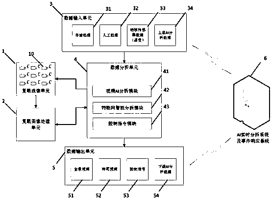
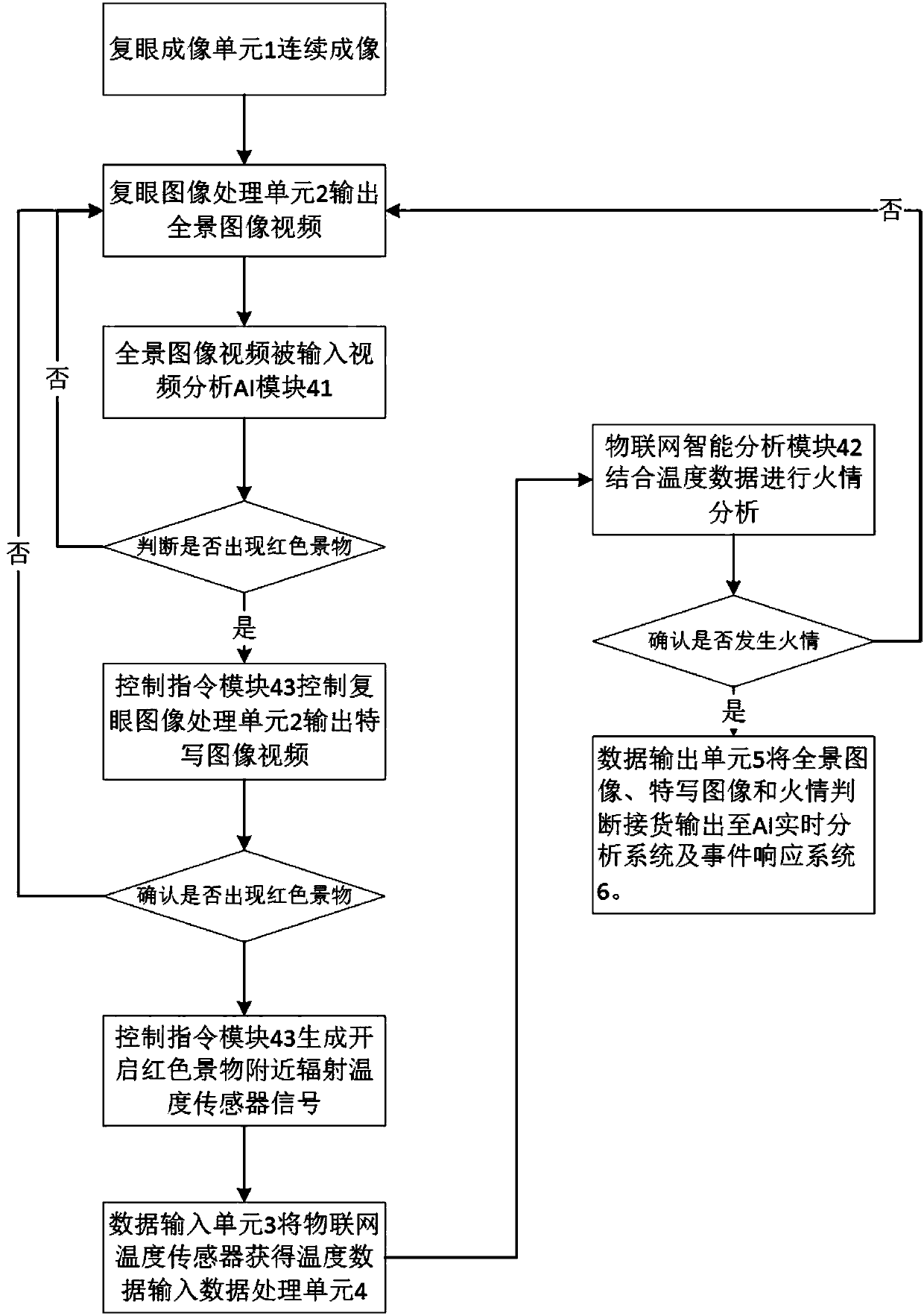
[0097] figure 1 is a system structure diagram according to the first embodiment of the present invention. Figure 1a It is a flow chart of the panoramic image and close-up image output method in the first embodiment of the present invention. Combine below figure 1 and 1a This method will be described.

[0098] The intelligent monitoring system in this embodiment is used to monitor the occurrence of fire in the scene. The compound eye imaging unit 1 in this embodiment adopts 9×9 narrow field of view telephoto imaging subunits 10 to form an array, the focal length of each narrow field of view telephoto imaging subunit is 75mm, the field of view angle is 25°, and the output image The resolution is 1080P. The overall bandwidth of the compound eye imaging unit is 36Mbps. Input the 81 channels of 1080p main and sub streams captured by all 9×9 narrow field of view telephoto imaging sub-units 10 into the compound eye image reconstruction unit 20, and undergo storage, decoding, c...

no. 2 example

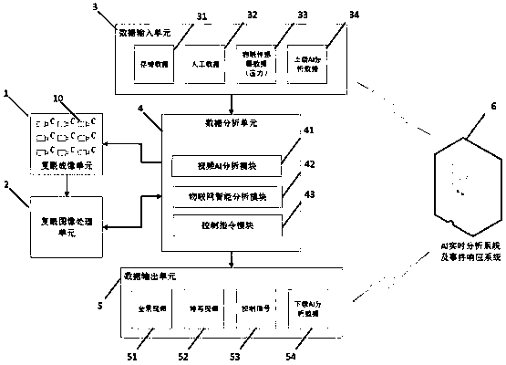
[0106] figure 2 is a system structure diagram according to the second embodiment of the present invention. Figure 2a It is a flow chart of the panoramic image and close-up image output method in the first embodiment of the present invention. Combine below figure 2 and 2a This method will be described.

[0107] The second embodiment proposed by the present invention is applied to vehicle monitoring. Same as the first embodiment, the compound eye imaging unit 1 in this embodiment adopts 9×9 narrow field of view telephoto imaging subunits 10 to form an array, the focal length of each narrow field of view telephoto imaging subunit is 75mm, and the field of view The field angle is 25°, and the resolution of the output image is 1080P. The overall bandwidth of the compound eye imaging unit is 36Mbps. Input the 81 channels of 1080p main and sub streams captured by all 9×9 narrow field of view telephoto imaging sub-units 10 into the compound eye image reconstruction unit 20, a...


PUM


Abstract

The invention discloses an intelligent compound eye monitoring system. The intelligent monitoring system can simultaneously output a panoramic image and a close-up image. The intelligent monitoring system comprises a compound eye imaging unit 1, a compound eye image processing unit 2, a data input unit 3, a data analysis unit 4 and a data output unit 5 as shown in figure 1. The compound eye imageprocessing unit 2 is used for reconstructing a compound eye image and generating a panoramic image and a close-up image. The data input unit 3 is used for obtaining stored data, manual data, Internetof Things sensor data and superior AI analysis data; The data analysis unit 4 combines the data acquired by the data input unit 3 with the panoramic image and the close-up image generated by the compound eye image processing unit 2 for analysis, and generates corresponding control information; And the data output unit 5 is used for outputting a panoramic image, a close-up image, control information and an intelligent analysis result.

Description

technical field [0001] The invention relates to the technical field of video monitoring and pattern recognition, in particular to an intelligent monitoring system capable of simultaneously outputting panoramic images and close-up images. Background technique [0002] With the progress of society and the development of science and technology, the traditional video surveillance system can no longer meet the current monitoring needs. Traditional video surveillance systems usually use a camera to monitor a fixed area. When the monitoring distance is long and the area is large, this monitoring system can only obtain general information about the monitoring scene, such as faces and license plates. Detailed information makes it impossible for the monitoring system to clearly record and show the suspicious situations captured by the shooting to the monitoring personnel, resulting in the failure of the monitoring system to play its due role. [0003] One of the existing solutions is...

Claims


Application Information

Patent Timeline
Patent Type & Authority Applications(China)
IPC IPC(8): G06T5/50G06K9/46G06K9/62H04N7/18
CPCH04N7/181G06T5/50G06T7/11G06T7/30G06T2207/20221G06T2207/20132G06V10/40G06F18/21
Inventor 金虹辛贾伟
Owner 小元感知(无锡)科技有限公司
Why Eureka
Try Eureka