Phase modifier configuration method of ultrahigh-voltage DC sender power grid

An ultra-high voltage DC, configuration method technology, applied in circuit devices, AC network circuits, power transmission AC networks, etc., can solve problems such as insufficient responsiveness

Active Publication Date: 2019-04-16
STATE GRID LIAONING ELECTRIC POWER RES INST +2
View PDF3 Cites 12 Cited by
  • Summary
  • Abstract
  • Description
  • Claims
  • Application Information

AI Technical Summary

Problems solved by technology

However, with the implementation of the UHV DC project, the hazards of power frequency overvoltage control at the sending end, chain reaction at the receiving end grid, and commutation failure are gradually increasing. State output requirements, preventing commutation failure and fast large-capaci

Method used


Image

  • Phase modifier configuration method of ultrahigh-voltage DC sender power grid
  • Phase modifier configuration method of ultrahigh-voltage DC sender power grid
  • Phase modifier configuration method of ultrahigh-voltage DC sender power grid

Examples


Embodiment Construction

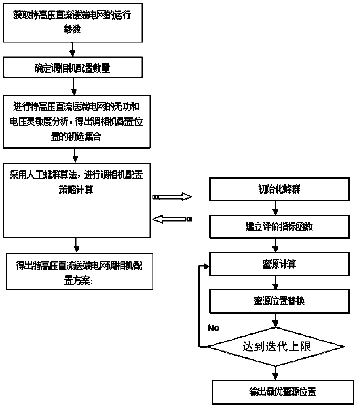
[0080] Such as Figure 1 to Figure 4 As shown in the present invention, a method for configuring the condenser of the UHV DC sending-end power grid in the present invention refers to realizing UHV DC power transmission in the UHV DC sending-end grid based on the voltage dynamic characteristics of the system and through the optimal configuration of the condenser. The stable operation of the system voltage includes the following steps:

[0081] Step 1. Obtain the operating parameters of the UHV DC sending end power grid;

[0082] Step 2. Determine the configuration quantity of the condenser;

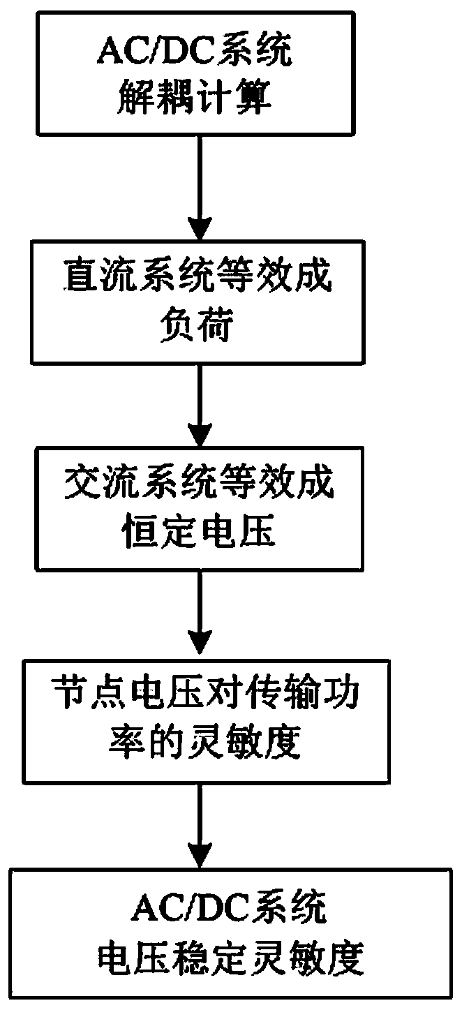
[0083] Step 3. Carry out reactive power and voltage sensitivity analysis of the UHVDC sending-end power grid, and obtain a primary selection set of condenser configuration positions;

[0084] a. Calculate the sensitivity of the reactive power injection point and the AC bus voltage of the DC converter station;

[0085] b. Calculate the sensitivity of the reactive power injection point an...


PUM


Abstract

The invention belongs to the technical field of power grid operation and control, in particular to a phase modifier configuration method of an ultrahigh-voltage (UHV) DC sender power grid. The methodspecifically relates to a phase modifier configuration method of a UHV DC sender power grid. The method includes the following steps: acquiring the operation parameters of a UHV DC sender power grid;determining the configuration number of phase modifiers; analyzing the reactive power and voltage sensitivity of the UHV DC sender power grid to obtain a primary set of phase modifier configuration positions; calculating out a phase modifier configuration strategy by using an artificial bee colony algorithm; and obtaining a phase modifier configuration strategy of the UHV DC sender power grid. Theconfiguration of phase modifiers in the UHV DC sender power grid can be realized more effectively, the voltage operation stability of the power grid can be improved, and a technical basis and a practical method are provided for the operation and control of the UHV DC sender power grid. With the increase of UHV AC/DC transmission systems, the development of reactive power optimal allocation strategies is bound to have greater demand and a good commercial development prospect.

Description

technical field [0001] The invention belongs to the technical field of power grid operation and control, and in particular relates to a method for configuring a condenser for an UHV DC sending-end power grid, in particular to a method for configuring a condenser for an UHV DC sending-end system grid. Background technique [0002] my country's primary energy and load are distributed in reverse. In order to meet the urgent needs of clean energy transmission, load center power supply, energy conservation and emission reduction, the State Grid has vigorously developed UHV AC and DC technologies suitable for long-distance and large-capacity transmission. The positioning of UHV AC and DC transmission projects and the long-distance and large-capacity transmission of large-scale energy bases have become the main ways to alleviate the contradiction between China's energy resources and economic layout. At present, my country is in the transition period of UHV power grid development. W...

Claims


Application Information

Patent Timeline
IPC IPC(8): H02J3/36H02J3/12
CPCH02J3/12H02J3/36H02J2203/20Y02E60/60
Inventor 王刚李家珏朱钰邵宝珠杨东升李鹏里叶鹏顾盈之
Owner STATE GRID LIAONING ELECTRIC POWER RES INST
Why Eureka
Try Eureka