Atomizing powdering device and atomizing powdering method

A technology for atomizing powder milling and equipment, which is applied in the direction of improving process efficiency and improving energy efficiency, etc., can solve the problems of molten steel hanging on the inner wall of the guide pipe, high cost, and affecting the atomization effect.

Active Publication Date: 2019-04-16
QINGDAO YUNLU ADVANCED MATERIALS TECH CO LTD
View PDF11 Cites 9 Cited by
  • Summary
  • Abstract
  • Description
  • Claims
  • Application Information

AI Technical Summary

Problems solved by technology

[0005] based on figure 1 The shown atomization equipment carries out atomization pulverization, has the following defects: 1) pulverization operation rate is low: smelting furnace, for example, the smelting furnace that can hold the quality of molten steel is 200-500kg, from melting raw material to molten steel to temperature, The preparation time is 90-100min; the milling time is 15-30min; the 24h continuous production milling time is only 3-4h
2) The cost of refractory materials (that is, refractory materials) is high, and the refractory materials need to be replaced every time molten steel is poured
However, in the actual milling process, the smelting furnace needs to prepare a new batch of molten steel after pouring one batch of molten steel into the spray ladle 130, and when the spray ladle 130 receives one batch of molten steel, that is, after 300kg of molten steel, due to the There is no heating device around the draft tube, so the molten steel flowing through the draft tube will gradually cool down, causing the molten steel to hang on the inner wall of the draft tube or block the draft tube. If a new batch of molten steel is prepared in the smelting furnace 120 In the future, if you continue to pour the spray bag 130, the atomization effect will be seriously affected. Therefore, even if the service life of the refractory material is not exhausted, the refractory material must be replaced

Method used


Image

  • Atomizing powdering device and atomizing powdering method
  • Atomizing powdering device and atomizing powdering method
  • Atomizing powdering device and atomizing powdering method

Examples


Embodiment Construction

[0054] In order to make the purpose, technical solutions and advantages of the embodiments of the present invention more clear, the technical solutions in the embodiments of the present invention will be described below in conjunction with the drawings in the embodiments of the present invention.

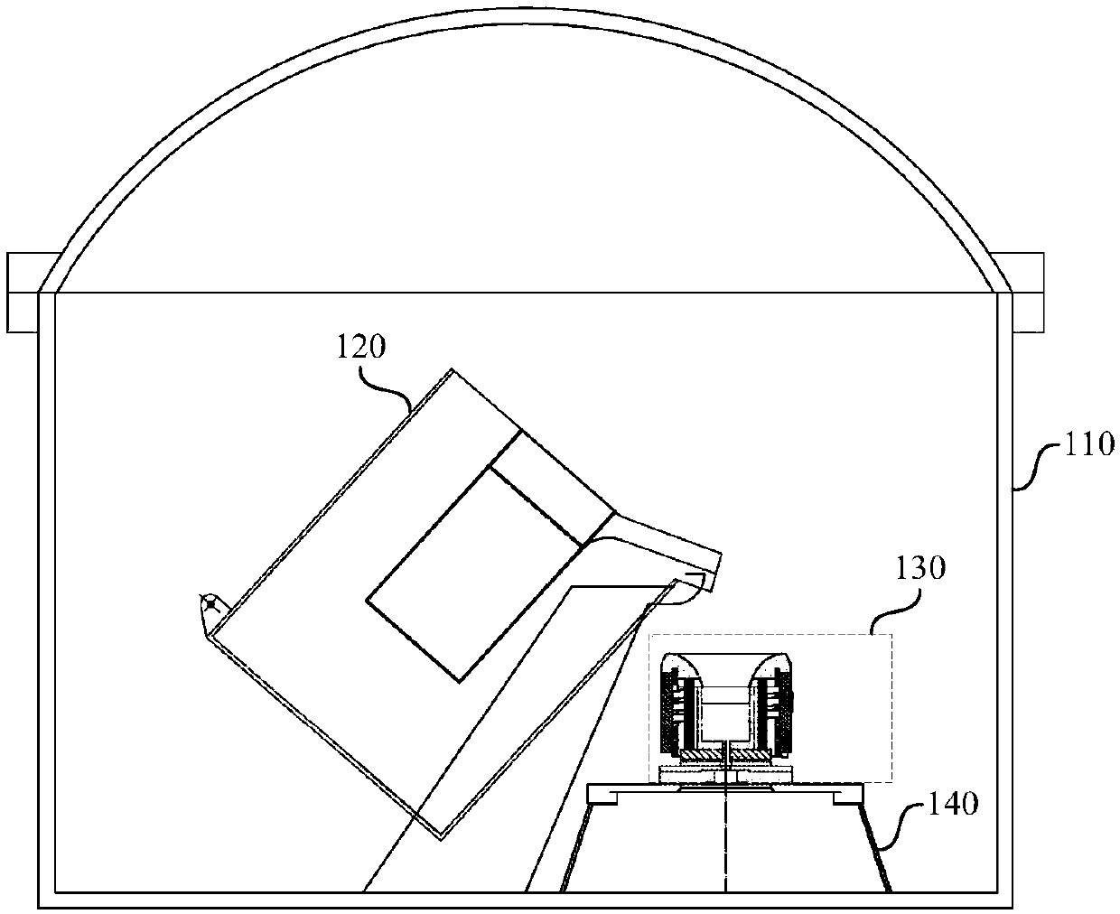
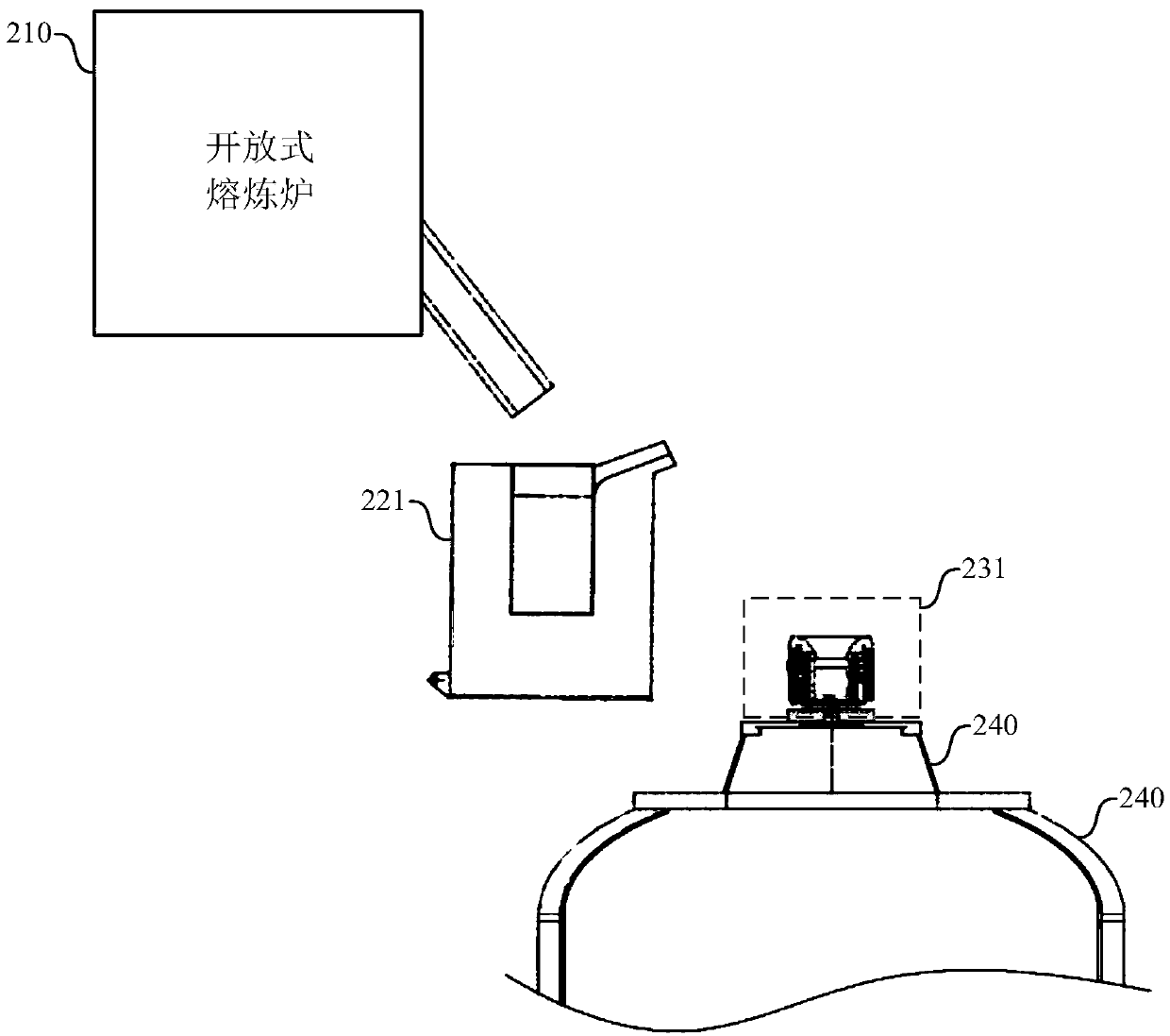
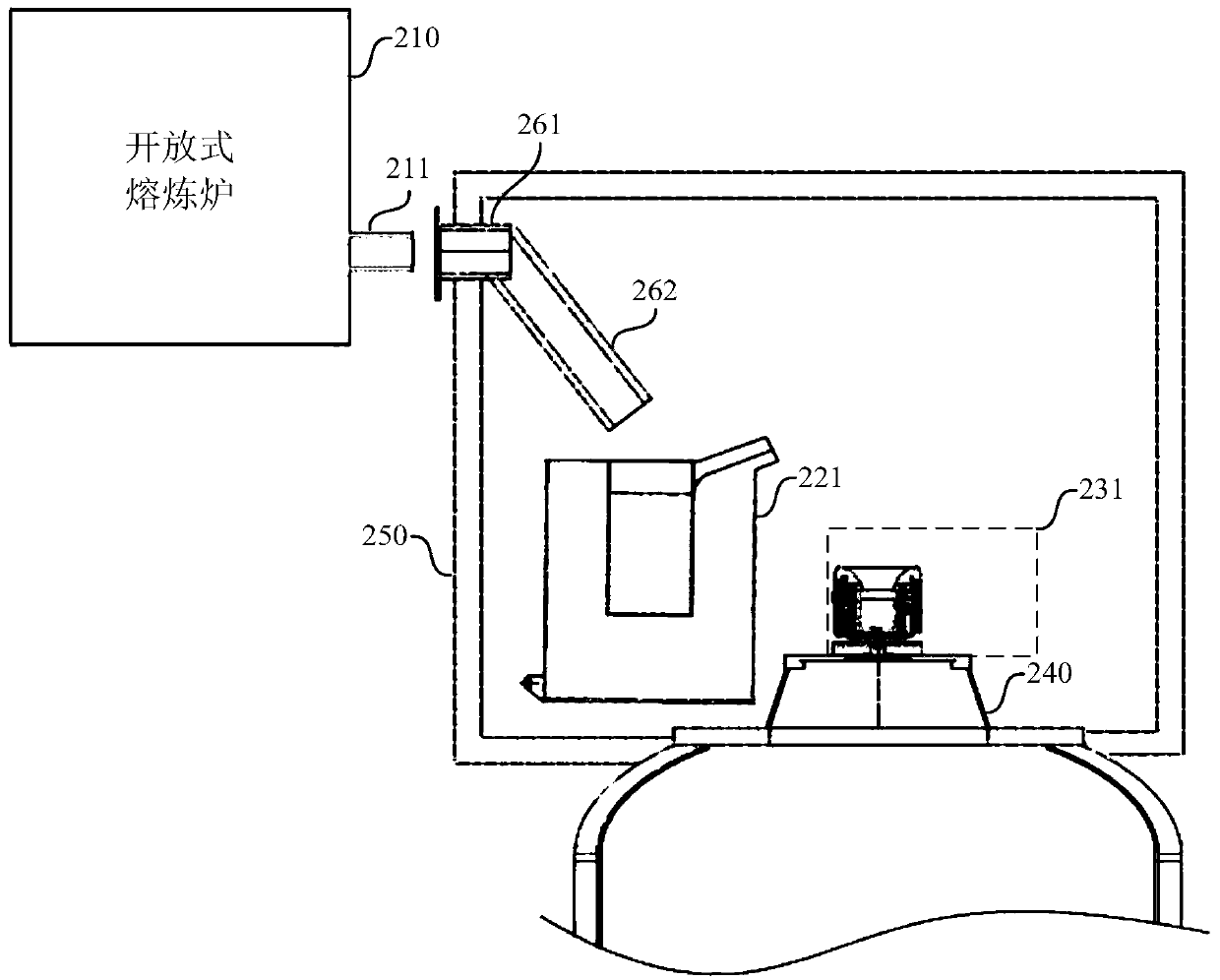
[0055] The embodiment of this specification proposes an atomized powder making equipment, which is designed with an open smelting furnace and a tundish, which is different from figure 1 The smelting furnace 120 shown in, in one embodiment, as figure 2 As shown, the open melting furnace 210 pours the molten steel into the tundish 221 after melting the molten steel, and then the tundish 221 pours the molten steel into the spray ladle 231 . Because raw materials can be continuously added to the open melting furnace to ensure that the molten steel therein is sufficient, so that after all the molten steel in the tundish 221 is poured into the spray ladle 231, the molten steel can be dir...


PUM


Abstract

A atomizing powdering is provided and is provided with an open smelting furnace used for melting steel and a tundish for receiving molten steel. The molten steel in the open smelting furnace is kept sufficient so that the tundish can quickly receive the molten steel from the furnace, thereby pouring a spray ladle. Further, on the one hand, a plurality of tundishes, such as two, can be designed such that the two tundishes can alternately receive molten steel from the open smelting furnace and carry out continuous multi-pack casting of the same spray ladle. On the other hand, multiple spray ladles can be designed to save time in replacing the spray ladles. In this way, the time and operation rate of the powdering process can be improved, and the refractory material in the spray ladles can besaved.

Description

technical field [0001] The embodiments of the present invention relate to the technical field of metal powder making, and in particular to an atomized powder making device and an atomized powder making method. Background technique [0002] Atomization powder production refers to the powder production method that breaks metal or alloy liquid into fine droplets by the impact of fast-moving fluid (atomization medium), and then condenses into solid powder. Atomized powder is the best way to produce fully alloyed powder, and its product is called pre-alloyed powder. Each particle of this powder not only has the same uniform chemical composition as the given molten alloy, but also refines the crystal structure due to rapid solidification, eliminating the macro-segregation of the second phase. [0003] The vacuum air atomization powder making method is a new type of process developed in the metal powder manufacturing industry in recent years. It has the advantages of not easy oxi...

Claims


Application Information

Patent Timeline
Patent Type & Authority Applications(China)
IPC IPC(8): B22F9/08
CPCB22F9/082B22F2009/0888B22F2009/0848Y02P10/20
Inventor 李晓雨庞靖张雪松费晶魏文喜
Owner QINGDAO YUNLU ADVANCED MATERIALS TECH CO LTD
Why Eureka
Try Eureka