Conductor line, current collector, conductor line system, and method for contactlessly transmitting data

A technology of data transmission and trolley line, which is applied in the field of trolley line, current collector, trolley line system and non-contact data transmission, which can solve the problems of unfavorable data transmission

Active Publication Date: 2019-04-16
CONDUCTIX WAMPFLER
View PDF15 Cites 2 Cited by
  • Summary
  • Abstract
  • Description
  • Claims
  • Application Information

AI Technical Summary

Problems solved by technology

This is based on the fact that the asymmetry of the bent longitudinal slots and the longer transmission path of the wave is not good for data transmission compared to straight longitudinal slots

Method used


Image

  • Conductor line, current collector, conductor line system, and method for contactlessly transmitting data
  • Conductor line, current collector, conductor line system, and method for contactlessly transmitting data
  • Conductor line, current collector, conductor line system, and method for contactlessly transmitting data

Examples


Embodiment Construction

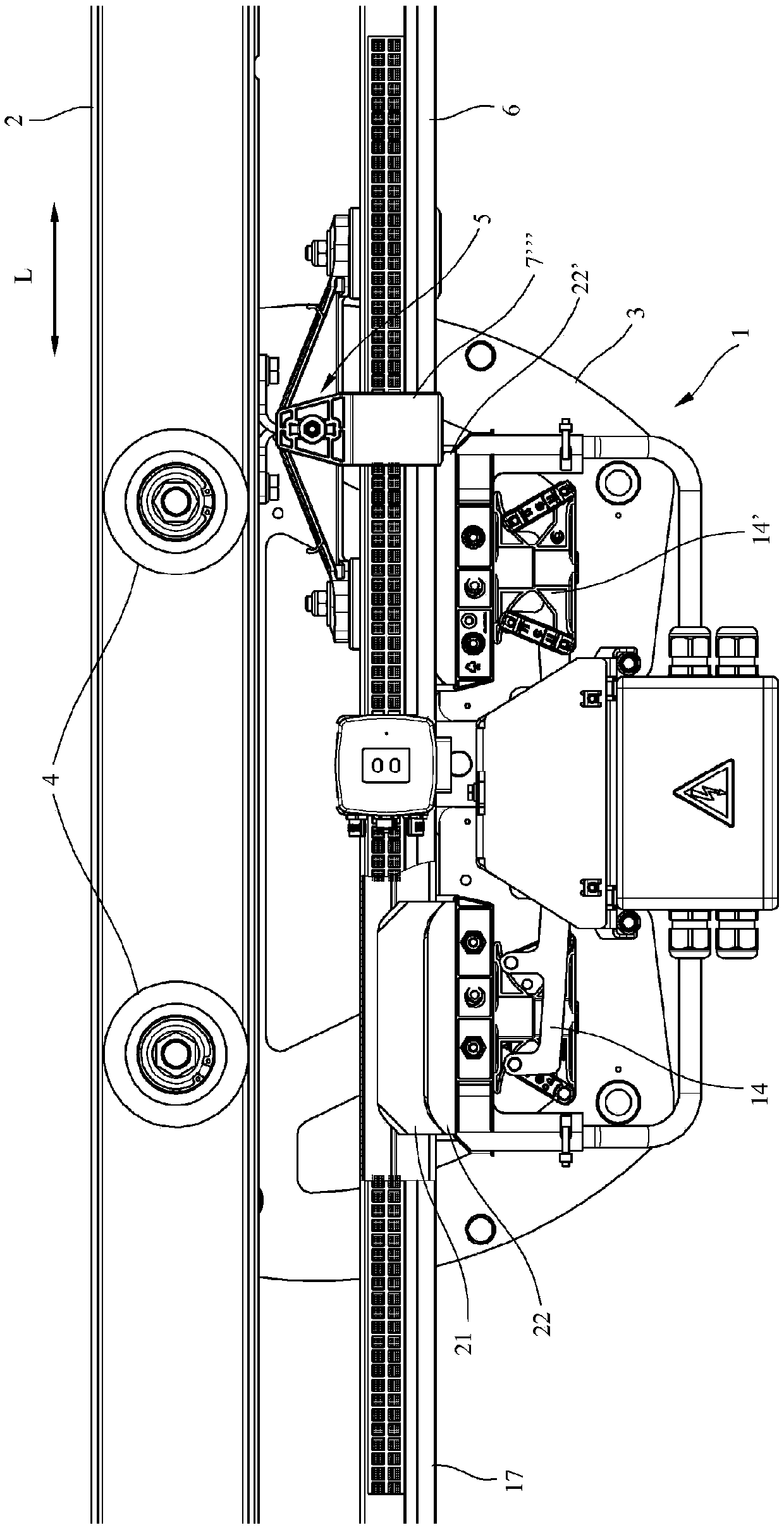
[0038] figure 1 A plan view from the side is shown of a part of a busbar system 1 according to the invention, the structure of which is substantially identical to the busbar system described in DE 10 2014 107 466 A1. This leads to the disclosure content of document DE 10 2014 107 466 A1—in this respect its accompanying figure 1 , 2 and 2a and the associated description - become the content of the present application.

[0039] The trolley line system 1 has a substantially double U-shaped track line 2 . The current collector 3 of an electrical load not shown on the track line 2 is movable in the longitudinal direction L by means of a pulley 4 . The current collector 3 is used to power electrical loads movable along the track line 2, such as container cranes.

[0040] On the underside of the track wire 2 , the trolley wire 6 according to the invention is mounted hanging downwards by means of trolley wire holders 5 arranged at a distance from one another in the longitudinal di...


PUM


Abstract

The invention relates to a conductor line (6; 35) for supplying electric energy to at least one electric load which can be moved on the conductor line (6; 35) in the longitudinal direction (L) of theconductor line, comprising at least one conductor strand (15) which runs in the longitudinal direction and which comprises an electrically conductive profiled conductor section (10, 16) for contactinga conductor contact (21, 22) of the load, and a current collector (3) for supplying electric energy to the at least one load, wherein the current collector (3) has at least one conductor contact (21,22) for contacting an electrically conductive profiled conductor section (10, 16) of a conductor strand (15) of the conductor line (6; 35). The aim of the invention is to allow a simple, secure, andextremely reliable data transmission which has as little interference as possible or is as interference-free as possible, is insensitive to external influences, and has a high transmission volume. This is achieved in that a first optical transmission unit (27) which runs in the longitudinal direction (L) is arranged on the conductor line (6; 35) for contactlessly transmitting data to a second optical transmission unit (30) which can be moved relative to the conductor line (6; 35), and a second optical transmission unit (30) which can be moved in the longitudinal direction (L) relative to the conductor line (6; 35) is arranged on the current collector (3) for contactlessly transmitting data to a first optical transmission unit (27) arranged on the conductor line (6; 35).

Description

technical field [0001] The invention relates to a trolley line according to the preamble of claim 1 , a current collector according to the preamble of claim 11 , a trolley line system according to the preamble of claim 17 and the preamble of claim 20 . The method for contactless data transmission of the prologue part. Background technique [0002] In known trolley line systems, a movable electrical load moves along the trolley line. To supply the load, the load is equipped with a collector whose sliding contact engages in a conductor bundle which is guided along the trolley line. The load can be, for example, a transport suspension of a track-mounted suspension track, a cable car movable on the track or an E-RTG-container crane, which is equipped with an electric running gear powered by trolley lines. [0003] In order to be able to transmit data from and to loads, such as control data, slotted waveguides / waveguide slot antennas / slotted hollow conductors are used in known ...

Claims


Application Information

Patent Timeline
Patent Type & Authority Applications(China)
IPC IPC(8): B60L5/36B60L5/40
CPCB60L5/36B60L5/40H04B10/1149B61L3/065H04B10/11H04B10/116
Inventor M·埃克尔
Owner CONDUCTIX WAMPFLER
Why Eureka
Try Eureka