Eye Diopter Measuring Device

A measuring device and diopter technology, applied in refractometers, retinal mirrors, etc., can solve problems such as complex calculation processes, achieve the effect of simplifying the calculation process and improving measurement efficiency

Active Publication Date: 2021-08-06
重庆远视科技有限公司
View PDF41 Cites 2 Cited by
  • Summary
  • Abstract
  • Description
  • Claims
  • Application Information

AI Technical Summary

Problems solved by technology

However, the calculation process of this method is complicated

Method used


Image

  • Eye Diopter Measuring Device
  • Eye Diopter Measuring Device
  • Eye Diopter Measuring Device

Examples


Embodiment Construction

[0040] In order to better understand the technical solution of the present invention, the technical solutions in the embodiments of the present invention will be described in connection with the drawings in the embodiments of the present invention. Embodiments are merely embodiments of the invention, not all of the embodiments. Based on the embodiments in the present invention, those of ordinary skill in the art will belong to the scope of the invention in the present invention without making in the pre-creative labor premise.

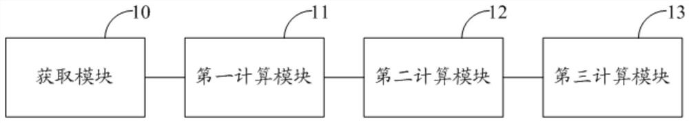
[0041] Embodiments of the present invention provide an eye diopter measuring device, including:

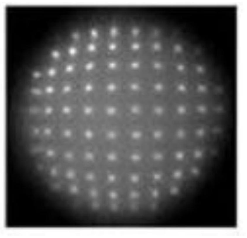
[0042] Get the module to get the spot array image of the eye to be tested;

[0043] The first computing module is configured to calculate the horizontal vector and vertical vector of the spear array image, respectively, respectively, respectively, respectively, respectively, the horizontal vector of the spot array image characterizes the horizontal direction i...


PUM


Abstract

The invention discloses an eye diopter measurement device, the acquisition module is used to acquire the spot array image of the eye to be measured, and the first calculation module is used to calculate the horizontal vector and the vertical vector of the spot array image, which are respectively recorded as the first horizontal vector and the second A vertical vector, the second calculation module is used to construct the first matrix with the first horizontal vector and the first vertical vector, construct the second matrix with the second horizontal vector and the second vertical vector, and construct the third matrix, the third calculation module It is used to calculate the diopter of the eye to be tested according to the preset relationship satisfied by the third matrix and the diopter. The eye diopter measurement device disclosed in the present invention converts the image information into a matrix according to the obtained eye spot array image to be measured, and obtains the diopter information by calculating the matrix orthogonal transformation. Compared with the existing method, the calculation process of obtaining the eye diopter More simplified, which helps to improve measurement efficiency.

Description

Technical field [0001] The present invention relates to the field of eye detection, and in particular, to an eye diopter measuring device. Background technique [0002] The role of the eye refractive light is referred to as refractive. The eye is a visual organ that is adapted to the stimulus. From the optical angle, the eye can be seen as an optical system, the external object emits or reflects light, and after the eyeball will generate refraction, a clear reduction image is formed on the retina. However, the adjusted eyes will cause parallel light incident into the eyeball to the front or rear of the retina, thereby forming refractive. The refractive capacity of the eye is used to use diopter, and the refractiveness is the reciprocal of the distant distance of the eye. [0003] In the prior art, the method of measuring the eye diopter is to use the Sharkhartman wave pre-sensor to acquire the spot array image of the eye, map the spot array image to an ellipse, and obtain the ref...

Claims


Application Information

Patent Timeline
Patent Type & Authority Patents(China)
IPC IPC(8): A61B3/103
CPCA61B3/103
Inventor 胡冰游磊
Owner 重庆远视科技有限公司
Why Eureka
Try Eureka