
Method for fast and accurately realizing concrete pump truck cantilever crane movement locus

A concrete pump truck and boom technology, which is applied to instruments, adaptive control, control/adjustment systems, etc., can solve the problems of complicated planning process of the movement trajectory of the boom end, cumbersome calculation, large amount of calculation, etc. Control, simple calculation process, fast algorithm effect

Inactive Publication Date: 2013-06-26
XUZHOU YANDA TRANSMISSION & CONTROL TECH
View PDF5 Cites 19 Cited by
  • Summary
  • Abstract
  • Description
  • Claims
  • Application Information

AI Technical Summary

Problems solved by technology

Reasonable planning of the motion trajectory of the boom end is one of the conditions for realizing the intelligent control of the boom. Since the pump truck boom system is a set of open-loop series mechanisms with multiple degrees of freedom in space, when planning the motion trajectory of the boom end, it is necessary to However, for multi-degree-of-freedom series mechanisms, the kinematics forward solution is relatively easy, and the inverse solution has always been a difficult point in the field of robotics. Currently, the inverse transformation method, geometric method, The minimum joint norm method, etc. Most of these methods need to solve a large number of nonlinear transcendental equations, so the solution speed is slow, and there are many sets of inverse solutions at the same time, and it is necessary to search for the optimal solution. The trajectory planning process of the end of the frame is complicated, the calculation is cumbersome, and the real-time performance is poor
Due to the limitation of the calculation speed of the general controller of construction machinery, the current motion trajectory planning method is difficult to implement

Method used


Image

  • Method for fast and accurately realizing concrete pump truck cantilever crane movement locus
  • Method for fast and accurately realizing concrete pump truck cantilever crane movement locus
  • Method for fast and accurately realizing concrete pump truck cantilever crane movement locus

Examples


Embodiment

[0035] The invention discloses a method for quickly and accurately realizing the movement trajectory of the arm frame of a five-section arm concrete pump truck. The specific steps are as follows:

[0036] step 1:

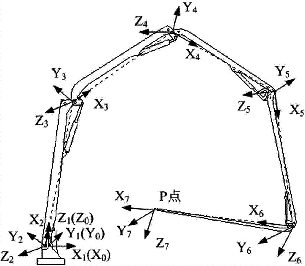
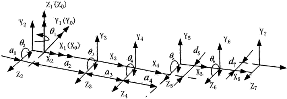
[0037] Establish the boom system coordinate system model. According to the structural model of the arm frame system of the five-section arm concrete pump truck, the joint coordinate system of the arm frame mechanism of the concrete pump truck is established, as shown in figure 1 As shown, a total of seven joint coordinate systems are established, and the pouring end of the boom is marked with point P, and its coordinates are (x 7 ,y 7 ,z 7 ). Measure the structural size of the boom to obtain the connecting rod parameters of the D-H matrix, as shown in Table 1.

[0038] Step 2:

[0039] Solve for the coordinates of P at the pouring end of the jib. Analysis of the jib coordinate system and connecting rod parameters shows that the coordinates of point P at the ...


PUM


Abstract

The invention discloses a method for fast and accurately realizing concrete pump truck cantilever crane movement locus. The method comprises the following steps: analyzing a movement space of the concrete pump truck cantilever crane, providing a regional planning law of the movement locus of a concrete pump truck cantilever crane system, reasonably dividing a working region of the cantilever crane, and selecting proper regional parameters, setting a transition area between adjacent regions, obtaining a target joint variable of the unique group of concrete pump truck cantilever crane system by searching the region of a tracing point, thereby substituting the traditional robot positive and inverse solution computation which can be completed by computing a large number of transcendental equations. By planning the movement locus of the concrete pump truck cantilever crane, the solution difficulty of the concrete pump truck cantilever crane system joint variable is greatly reduced, the method is a fast and accurate inverse solution algorithm, and has the characteristics of being high in automation degree and high in instantaneity.

Description

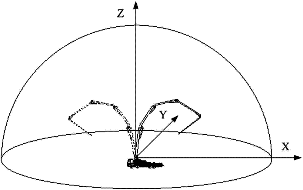
technical field [0001] The invention relates to a method for quickly and accurately realizing the movement track of the boom in the process of intelligent control of the boom of the concrete pump truck. Background technique [0002] At present, intelligent automatic pouring operation has become the development trend in the field of intelligent control of concrete pump truck boom. In the process of intelligent control of the boom of concrete pump truck, the reasonable planning of the trajectory of the boom is the premise of realizing intelligent control. The entire boom system of the concrete pump truck is driven by the hydraulic motor installed on the chassis to drive the slewing support, and the movement of each boom is driven by the hydraulic cylinder between the booms to drive the connecting rod mechanism, so as to realize various changes in the posture of the boom and complete the concrete. pouring. [0003] The concrete pump truck boom control system adjusts the displ...

Claims


Application Information

Patent Timeline
IPC IPC(8): G05B13/04
Inventor 高英杰刘荣升刘凯磊宁博
Owner XUZHOU YANDA TRANSMISSION & CONTROL TECH
Learn More