Operating table with multifunctional combined instrument table
A technology of operating bed and instrument table, which is applied in the field of operating bed, can solve problems such as large limitations, and achieve the effects of reasonable design, convenient and fast connection and separation, and ingenious structure
- Summary
- Abstract
- Description
- Claims
- Application Information
AI Technical Summary
Problems solved by technology
Method used
Image
Examples
Embodiment 1
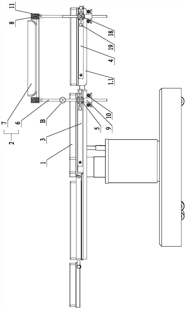
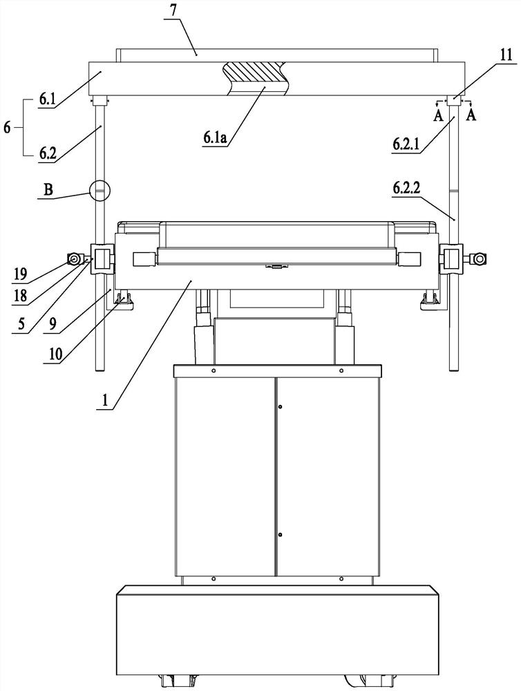
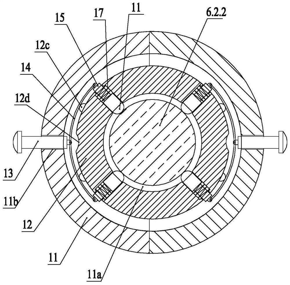
[0031] like Figure 1 ~ Figure 4 As shown, Embodiment 1 discloses an operating bed with a multifunctional combined instrument table, including an operating bed main body 1 and an instrument table 2, and first crossbars 3 are respectively provided on both sides of the middle part of the operating bed main body 1 , the outer sides of the two footboards 1.1 in the main body 1 of the operating bed are respectively provided with a second crossbar 4, and sliding blocks 5 are respectively slidably installed on the first crossbar 3 and the second crossbar 4; the instrument table 2 includes a bracket 6 and an instrument tray 7, the support 6 includes a top frame 6.1 and a vertical bar 6.2, the top frame 6.1 is rectangular, the instrument tray 7 is placed on the top frame 6.1, and the four borders of the top frame 6.1 T-shaped chute 6.1a is provided on the bottom of each frame, and the T-shaped chute 6.1a on the four frames communicates with each other. There are four vertical rods 6.2 ...
Embodiment 2
[0041] like Figure 5 , Image 6 As shown, Embodiment 2 discloses an operating bed with a multifunctional combined instrument table, which differs from Embodiment 1 in that the mechanism for adjusting the lifting and lowering of the vertical rod 6.2 is improved.
[0042] like Figure 5 , Image 6 As shown, the sliding block 5 is provided with a vertical through groove, the vertical rod 6.2 includes a vertical rod lower section 6.2.2 and a vertical rod upper section 6.2.1, and the vertical rod lower section 6.2.2 is inserted in the vertical rod The outer wall of the lower section 6.2.2 of the vertical rod is provided with teeth, and the side of the lower section 6.2.2 of the vertical rod is provided with a gear 21. The gear 21 is rotatably installed in the sliding block 5, and the gear 21 and the The teeth mesh; the center of the gear 21 is connected with a rotating shaft 22 , the rotating shaft 22 is rotatably mounted on the sliding block 5 , and a hand wheel 23 is mounted ...
PUM
 Abstract
Description
Claims
Application Information
 - R&D
- Intellectual Property
- Life Sciences
- Materials
- Tech Scout
- Unparalleled Data Quality
- Higher Quality Content
- 60% Fewer Hallucinations
Browse by: Latest US Patents, China's latest patents, Technical Efficacy Thesaurus, Application Domain, Technology Topic, Popular Technical Reports.
© 2025 PatSnap. All rights reserved.Legal|Privacy policy|Modern Slavery Act Transparency Statement|Sitemap|About US| Contact US: help@patsnap.com


