Eureka AIR delivers breakthrough ideas for toughest innovation challenges, trusted by R&D personnel around the world.

Passive transmission power generation communication device and passive intelligent brake shoe with same

A communication device, iron shoe technology, applied in circuit devices, battery circuit devices, current collectors, etc., can solve the problems of inconvenient disassembly, difficult to detect in advance, complicated to use, etc.

Pending Publication Date: 2019-04-19
XINYUN PROJECT OF CHINA RAILWAY FIRST GROUP +1
View PDF0 Cites 0 Cited by
  • Summary
  • Abstract
  • Description
  • Claims
  • Application Information

AI Technical Summary

Problems solved by technology

[0004] 1) The use of radio frequency identification technology means at least the need to use the corresponding reader, which greatly increases the economic cost of iron shoes;
[0005] 2) The existing smart iron shoes need to use a power supply when they are in use, which means that a small power supply needs to be added to the smart iron shoes to realize it. However, if a small power supply is installed, it means that the small power supply needs to be replaced after a period of use , it is very inconvenient to disassemble, and the replacement of the battery further increases the economic cost of iron shoes;
[0006] 3) When the battery power of the smart iron shoes is insufficient, it is difficult to detect in advance. The iron shoes need to be placed outdoors for a long time after being placed. If the power is insufficient, it is easy to cause misjudgment by the staff and cause losses;
[0007] 4) The structure is complex, and the staff need special training when using it, which is complicated to use

Method used


Image

  • Passive transmission power generation communication device and passive intelligent brake shoe with same
  • Passive transmission power generation communication device and passive intelligent brake shoe with same
  • Passive transmission power generation communication device and passive intelligent brake shoe with same

Examples


Embodiment 1

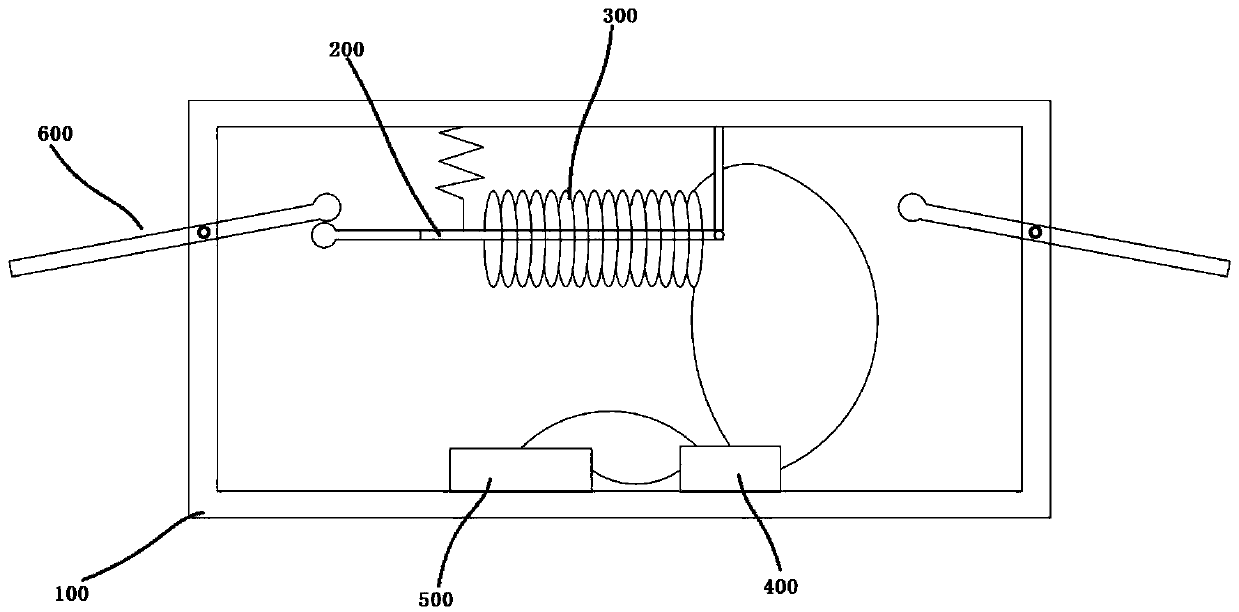
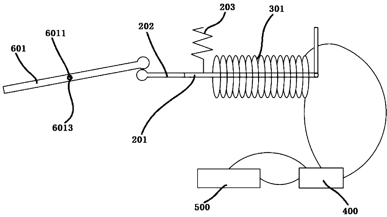
[0124] In this example, please refer to figure 1 , 2 , the transmission generating trigger part 600 touches the magnetic part 200 to make it move.

[0125] The magnetic part 200 is a magnetic rod 201, and the cutting part 300 is a coil 301;

[0126] The coil 301 is fixedly connected to the inner wall of the housing 100. It should be noted here that the coil 301 is fixed on the inner wall of the housing 100 through an insulating material, so that the housing 100 will not leak electricity. At the same time, the housing 100 can also be Made of insulating material, the two ends of the coil 301 are connected to the two ends of the rectifying and filtering module 400;

[0127] One end of the magnetic rod 201 is rotatably connected to the inner wall of the housing 100, and the other end is fixedly connected to a contact piece 202, and the magnetic rod 201 is also fixedly connected to the inner wall of the housing 100 through an elastic member 203;

[0128] The contact piece 202 is...

Embodiment 2

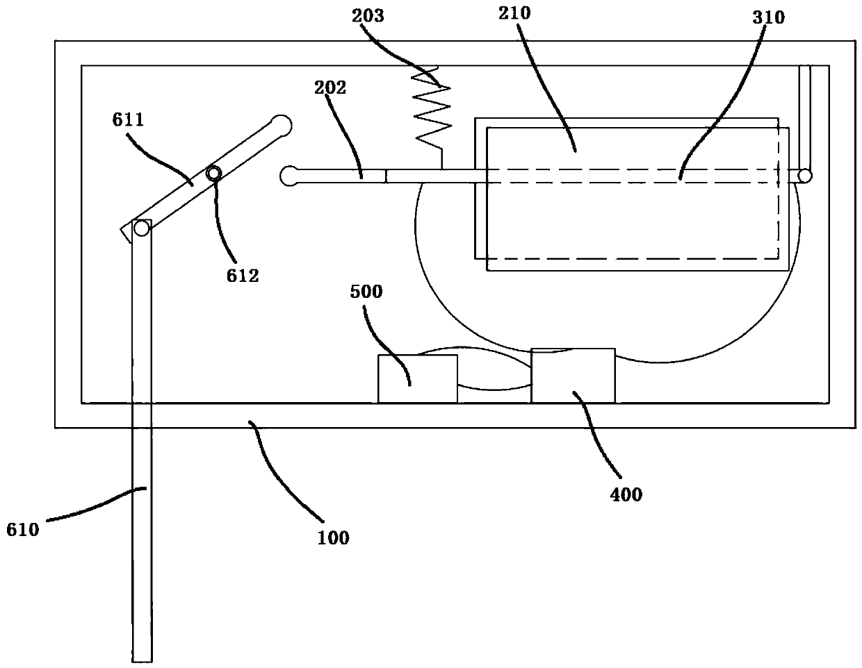
[0135] In this example, please refer to image 3 , 5 , the transmission power generation trigger part 600 touches the cutting part 200 to make it move.

[0136] The magnetic part 200 is two magnetic blocks 210 with opposite polarities, and the cutting part 300 is a metal rod 310;

[0137] The two magnetic blocks 210 are symmetrically arranged on the inner wall of the housing 100, and the space between the two magnetic blocks 210 forms a cutting space for the movement of the metal rod 310. The metal rod 310 acts on the transmission power generation trigger part 600 in the cutting space. Next, the metal rod 310 moves relative to the housing 100, thereby cutting the magnetic field lines of the two magnetic blocks 210 to generate an induced current;

[0138] One end of the metal rod 310 is rotatably connected to the inner wall of the housing 100, and the other end is fixedly connected to the contact piece 202, and the metal rod 310 is also fixedly connected to the inner wall of ...

Embodiment 3

[0152] In this example, please refer to Figure 7 , 8 , the fixing mechanism 710 is fixedly connected to the upper surface of the bottom plate 700, and the fixing mechanism 710 includes:

[0153] At least one base 711, the base 711 is fixedly connected to the upper surface of the bottom plate 700, and

[0154] at least one pillar 712, the bottom of the pillar 712 is fixedly connected with the top of the base 711, and

[0155] One fixed plate 713 , the bottom surface of the fixed plate 713 is fixedly connected with the top of the pillar 712 , and the passive transmission power generation and communication device is arranged on the bottom surface of the fixed plate 713 .

[0156] At least one opening is opened on the bottom plate 700. The purpose of the opening is to allow the trigger 800 to pass through the bottom plate 700. When the bottom of the bottom plate 700 fits the outer contour of the rail, the trigger 800 is lifted by the rail. , so as to trigger the passive transm...


PUM


Abstract

The invention discloses a passive transmission power generation communication device and a passive intelligent brake shoe with the same. The passive transmission power generation communication devicecomprises a shell, a magnetic portion, a cutting portion, a rectifier filter module, a communication portion and a transmission power generation trigger portion. The communication portion comprises asingle-chip microcomputer and a wireless communication module. The transmission power generation trigger portion penetrates the shell and is capable of moving relative to the shell and at least matched with one of the magnetic portion and the cutting portion to make the same move, and then the cutting portion cuts magnetic induction lines of the magnetic portion. The passive intelligent brake shoeis simple in structure and convenient to use, troublesome power source demounting and replacement are avoided due to freeness of an internal power source, and accordingly energy saving is realized. In addition, whether the passive intelligent brake shoe closely fits a rail or not can be effectively monitored to guarantee that causalities and property loss caused by inappropriate placement of thebrake shoe are avoided.

Description

technical field [0001] The invention relates to the technical field of vehicle anti-skidding, in particular to a passive transmission power generation communication device and passive smart iron shoes including the same. Background technique [0002] The slipping accident of railway vehicles is one of the frequently-occurring accidents in railway operation, and it belongs to the inertial accident. In order to prevent vehicles from moving and slipping away, and reduce casualties and property losses, the railway sector currently uses anti-slip iron shoes. When in use, the anti-skid shoes are usually placed under the wheels, and the tread resistance effect of the anti-skid shoes is used to stop the vehicle from moving. Because anti-slip iron shoes have the characteristics of firm material and easy to carry, they are generally adopted by railway departments. During the use of anti-skid iron shoes (hereinafter referred to as iron shoes), the most important thing is to confirm w...

Claims


Application Information

Patent Timeline
IPC IPC(8): B61K7/16H02J7/32
CPCB61K7/16H02J7/32
Inventor 乔朋李育朝宁善佑王战群段灵峰韩文利
Owner XINYUN PROJECT OF CHINA RAILWAY FIRST GROUP
Why Eureka
Eureka Blog
Learn More