Trajectory control strategy on-orbit correction method and system based on thruster deviation estimation

A thruster and orbit control technology, which is applied to aircraft, transportation and packaging, space navigation equipment, etc., can solve problems such as large interference of orbit control thrusters, changes in quality characteristics, and influence on orbit control accuracy, and achieve minimum orbit control interference The effects of simplification, improvement of accuracy and efficiency, and reduction of propellant consumption

Active Publication Date: 2019-04-19
SHANGHAI AEROSPACE CONTROL TECH INST
View PDF20 Cites 9 Cited by
  • Summary
  • Abstract
  • Description
  • Claims
  • Application Information

AI Technical Summary

Problems solved by technology

However, in the actual satellite development process, due to the general changes in the mass characteristics and installation requirements of the load and stand-alone aircraft, the final mass characteristics will change greatly, and the position of the center of mass may differ from the original design by a few centimeters to dozens centimeter
The design and production of thrusters are relatively mature, and generally do not change. Therefore, the final thruster installation layout may not match the position of the center of mass of the entire star, resulting in large interference generated by the orbital thruster itself, affecting the accuracy of attitude control, and then affecting orbit control. Accuracy, and need to consume additional fuel to balance the disturbance torque generated by the orbital thruster
In addition, a large amount of propellant will be consumed during orbit control, which will also cause the center of mass of the entire star to change, affecting the next orbit control effect

Method used


Image

  • Trajectory control strategy on-orbit correction method and system based on thruster deviation estimation
  • Trajectory control strategy on-orbit correction method and system based on thruster deviation estimation
  • Trajectory control strategy on-orbit correction method and system based on thruster deviation estimation

Examples


Embodiment Construction

[0039] In order to make the object, technical solution and advantages of the present invention clearer, the embodiments disclosed in the present invention will be further described in detail below in conjunction with the accompanying drawings.

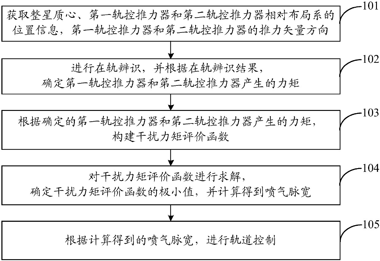
[0040] Such as figure 1 , in this embodiment, the on-orbit correction method of the orbit control strategy based on thruster bias estimation includes:

[0041] Step 101, obtain the position information of the center of mass of the entire star, the first orbital thruster and the second orbital thruster relative to the layout system; and obtain the thrust vector directions of the first orbital thruster and the second orbital thruster.

[0042] In this embodiment, the ground measurement results can be obtained first; then, the position information of the center of mass of the entire star, the first orbital control thruster and the second orbital control thruster relative to the layout system can be obtained through screening from the grou...


PUM


Abstract

The invention discloses a method and system for on-orbit correction of a track control strategy based on thruster deviation estimation. The method comprises the following steps: respectively acquiringthe position information of the center of mass of a whole satellite, a first orbit control thruster and a second orbit control thruster relative to a layout system; acquiring thrust vector directionsof the first orbit control thruster and the second orbit control thruster; carrying out on-orbit identification, and determining moments generated by the first orbit control thruster and the second orbit control thruster according to an on-orbit identification result; constructing an interference torque evaluation function; solving the interference torque evaluation function, determining the minimum value of the interference torque evaluation function, and calculating to obtain jet pulse width; and performing orbit control according to the calculated jet pulse width. According to the invention, an orbit control thrust distribution strategy is updated on orbit by adopting an energy optimization principle, and the minimization of orbit control interference is realized.

Description

technical field [0001] The invention belongs to the technical field of orbit control, and in particular relates to an orbit control strategy on-orbit correction method and system based on thruster deviation estimation. Background technique [0002] Generally speaking, the design of satellite platforms is based on the load requirements. Most of the loads have certain requirements on the orbital accuracy of the satellite, and the initial low launch of the satellite, the impact of orbital perturbation during the orbit operation, etc. will make the actual orbit There is a certain deviation from the nominal orbit, so the satellite platform is required to have orbit control capabilities. [0003] Ideally, the orbit control thruster should only generate thrust in the required direction, without generating additional force and moment on the satellite. Therefore, it is necessary to comprehensively consider the mass characteristics of the satellite and the installation layout of the t...

Claims


Application Information

Patent Timeline
Patent Type & Authority Applications(China)
IPC IPC(8): B64G1/24B64G1/26
CPCB64G1/242B64G1/26
Inventor 刘川牛睿陈敏花郑梦兴李圣文
Owner SHANGHAI AEROSPACE CONTROL TECH INST
Why Eureka
Try Eureka