An adjustable flow device simulating the nozzle of an aeroengine

An aero-engine and adjustable technology, which is applied in the direction of machine/engine, jet propulsion device, jet engine test, etc., can solve the problem that the dynamic performance of butterfly valve aerodynamic flow field is greatly affected, the control logic of multi-flap valve is complicated, and the valve body of sleeve valve Complicated structure and other problems, to achieve the effect of reducing the risk of motion sticking, good quality of flow field, and good quality of intake and exhaust airflow

Active Publication Date: 2021-08-03
AECC SICHUAN GAS TURBINE RES INST
View PDF6 Cites 0 Cited by
  • Summary
  • Abstract
  • Description
  • Claims
  • Application Information

AI Technical Summary

Problems solved by technology

The uneven exhaust of the butterfly valve has a great influence on the dynamic performance of the aerodynamic flow field; the diaphragm valve has a limited service life in a high temperature environment; the Y-type valve is large in size and cannot be used in a large-diameter engine; the control logic of the multi-flap valve is complex , the processing cost is high; the sleeve valve has a high risk of sticking in the high-temperature flow field due to the complex structure of the valve body, and these valves are restricted to varying degrees as engine nozzle simulation devices

Method used


Image

  • An adjustable flow device simulating the nozzle of an aeroengine
  • An adjustable flow device simulating the nozzle of an aeroengine
  • An adjustable flow device simulating the nozzle of an aeroengine

Examples


Embodiment Construction

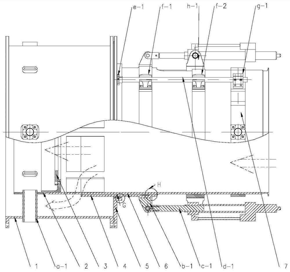
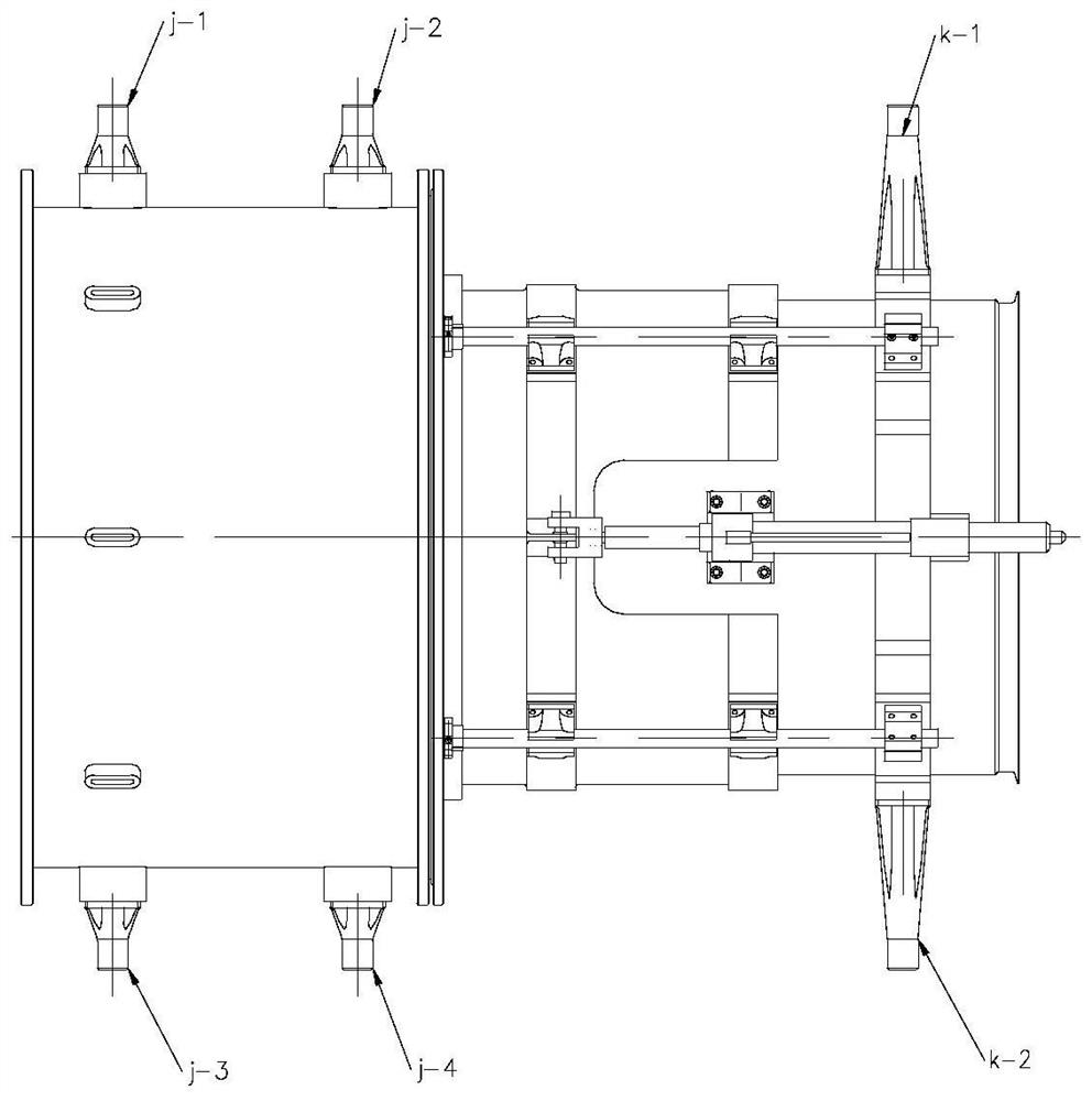
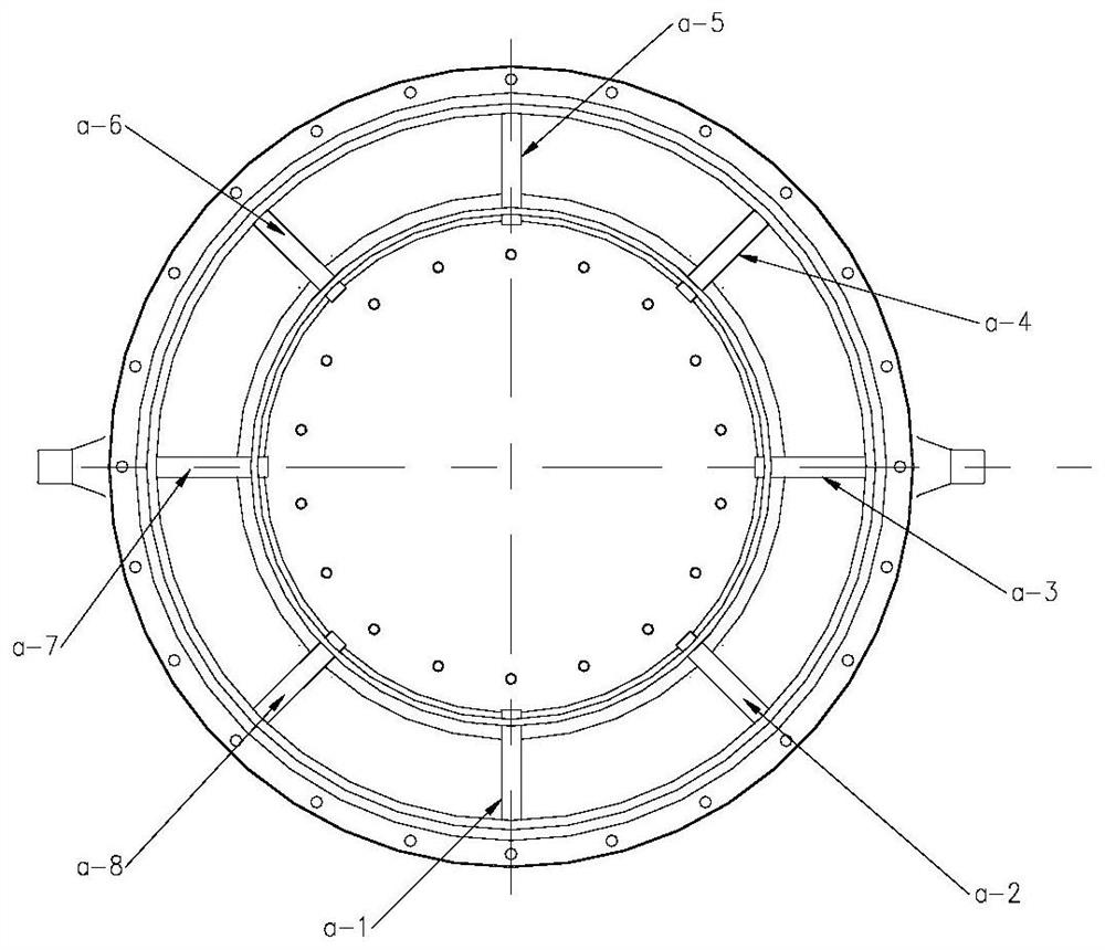
[0027] The following will refer to the attached Figure 1-5 Describe in detail the adjustable flow device simulating an aeroengine nozzle of the present invention. The adjustable flow device of the present invention comprises a nozzle outer tube 1, a nozzle inner tube 2, a normally open through hole 3, a movable sleeve 4, a sealing head 5, a straight nozzle tube 6, a straight outer fixed ring 7, a fixed cascade 1, a One sleeve lower lug seat b-1, the first lower drive cylinder c-1, the first guide rail d-1, the first head guide rail seat e-1, the sleeve guide rail bearing seat 1, the second sleeve guide rail bearing seat f-2, the first upper drive cylinder fixing seat h-1, the first straight guide rail fixing seat g-1, the trunnion j-1 installed on the first outer cylinder, the trunnion j-2 installed on the second outer cylinder, the third outer cylinder The barrel mounts a trunnion j-3, the fourth outer barrel mounts a trunnion j-4, the first straight barrel mounts a trunnio...


PUM


Abstract

Disclosed is an adjustable flow device simulating an aeroengine nozzle, the adjustable flow device comprising: a nozzle body, the nozzle body includes an axial inlet end and an axial outlet end; an axially normally open through hole, a normally open through hole Located at the axial outlet end of the nozzle body; the lateral adjustable through hole is arranged on the nozzle body along the circumferential direction, and the lateral adjustable through hole is closer to the nozzle than the normally open through hole. The axial inlet end of the pipe body; the adjustment assembly, the adjustment assembly is used to adjust the pore size of the lateral adjustable through hole, so as to simulate the throttling condition of the aeroengine nozzle; the fixing assembly, the adjustment assembly is fixed to the nozzle through the fixing assembly on the tube body.

Description

technical field [0001] The invention relates to an adjustable flow device, in particular to an adjustable flow device for simulating an aeroengine nozzle in a wind tunnel test or an aeroengine test. Background technique [0002] Aeroengine exhaust device (referred to as nozzle), its main function is to accelerate the expansion of high-temperature, high-pressure gas after the turbine and discharge it from the body; another function is to change the distribution of the gas expansion ratio in the turbine and nozzle by adjusting the area of ​​the nozzle , in order to realize the control of the working state of the engine. [0003] In the process of aero-engine component tests and wind tunnel tests, an adjustable flow device that simulates the work of the engine nozzle is needed to complement the adjustable exhaust function of the real nozzle and realize the experimental research on other components. Limited by the high-temperature and high-speed air / gas medium, the traditional ...

Claims


Application Information

Patent Timeline
Patent Type & Authority Patents(China)
IPC IPC(8): F02K1/06F02K1/08F02K1/15G01M15/14
CPCF02K1/06F02K1/08F02K1/15G01M15/14
Inventor 陈鹏飞吴锋钟华贵杨斐聂建平张大明
Owner AECC SICHUAN GAS TURBINE RES INST
Why Eureka
Try Eureka