Ventilation vortex reducer and wind turbine blade internally provided with same

A technology of wind turbine blades and blades, applied in the field of wind turbines, can solve the problems of reducing the performance of wind turbine blades, increasing the resistance of wind turbine blades, and increasing resistance, so as to improve the efficiency of wind energy capture, delay the stall situation, and reduce the intensity of wake vortex Effect

Inactive Publication Date: 2019-04-19
南通河海大学海洋与近海工程研究院 +1
View PDF5 Cites 0 Cited by
  • Summary
  • Abstract
  • Description
  • Claims
  • Application Information

AI Technical Summary

Problems solved by technology

[0006] The purpose of the present invention is to address the deficiencies of the above-mentioned background technology, to provide a ventilation vortex reduction device and a wind turbine blade built with the ventilation vortex reduction device, which not only realizes the delay of the surface stall phenomenon of the wind turbine blade at a large angle of attack, but also It avoids the defect that the ventilation vortex reduction device increases the resistance of wind turbine blades at small angles of attack, and solves the problem that although the existing vortex generators externally placed on the surface of the blades can increase the lift and reduce drag at large angles of attack, they cannot The technical problem of reducing the performance of wind turbine blades by increasing drag when cornering

Method used


Image

  • Ventilation vortex reducer and wind turbine blade internally provided with same
  • Ventilation vortex reducer and wind turbine blade internally provided with same
  • Ventilation vortex reducer and wind turbine blade internally provided with same

Examples


Embodiment Construction

[0028] The technical solution of the invention will be described in detail below in conjunction with the accompanying drawings.

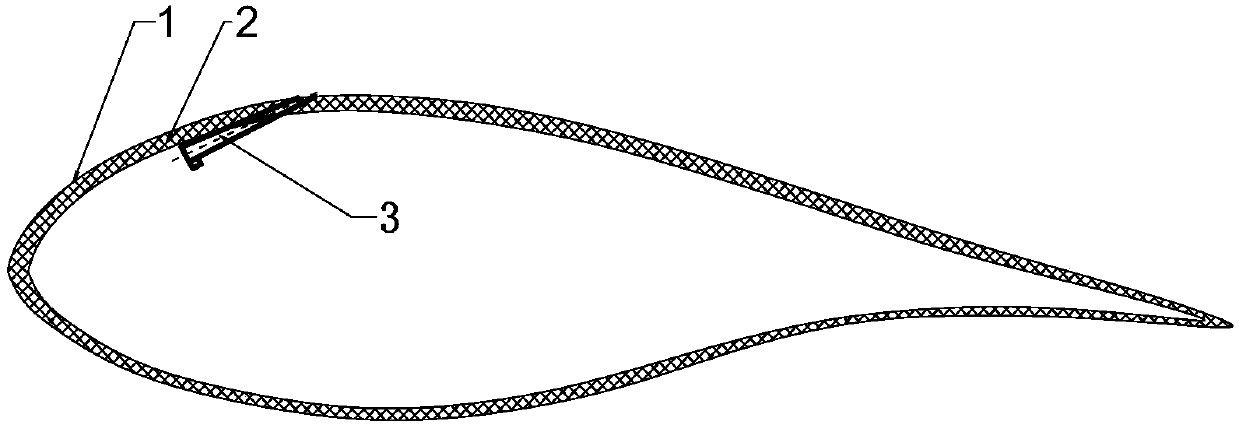
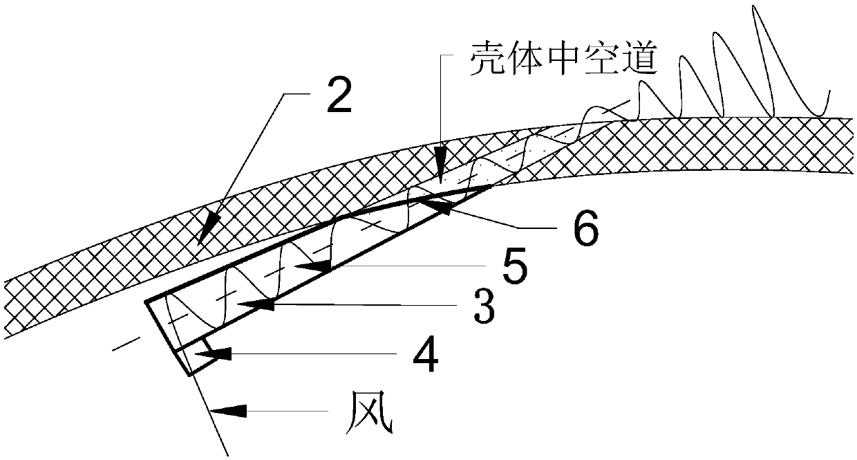
[0029] The wind turbine blade with the built-in ventilation and vortex reduction device disclosed by the present invention is as follows: figure 1 , Figure 10 As shown, the ventilation vortex reduction device 3 is located inside the airfoil section and runs through the elliptical small hole opened on the blade shell 2. The air in the hollow part of the blade flows through the ventilation vortex reduction device 3 under the action of the pressure difference between the inside and outside of the blade, and flows into the ventilation and vortex reduction device 3. The air of the vortex device 3 is guided by the device into a swirling flow and then discharged to the surface of the wind turbine blade 1 .

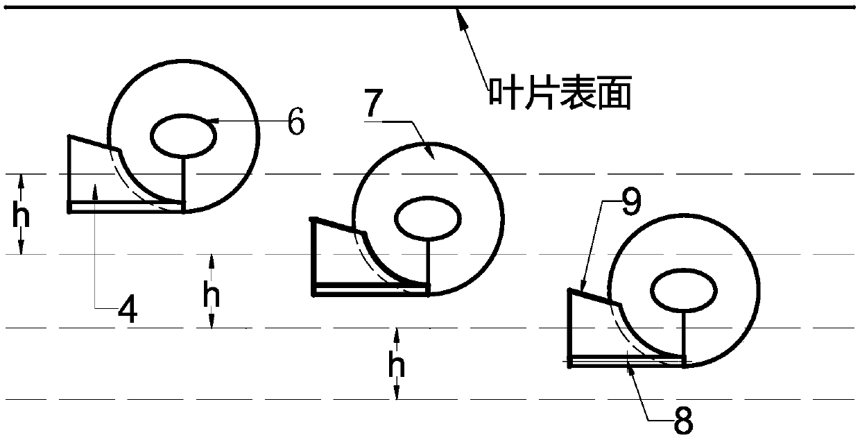
[0030] Ventilation vortex reduction device 3 such as figure 2 As shown, it is a spiral structure with a tapered cross section, and its main body i...


PUM


Abstract

The invention discloses a ventilation vortex reducer and a wind turbine blade internally provided with the same, and belongs to the technical field of wind turbines. According to the ventilation vortex reducer, the improvement design of the ventilation vortex reducer is provided aiming at the airflow separation phenomenon of the wind turbine blade, a section tapered round table wall surface internally provided with a spiral structure serves as a device body, and an air-duct tapered air inlet is formed in the side wall close to the large radius end of the round table wall surface. According tothe ventilation vortex reducer, enough air can be collected, and it is guaranteed that a vortex with sufficient strength can be produced through section changing and tangential inflowing. The invention further discloses the wind turbine blade internally provided with the ventilation vortex reducer. Device air outlets are attached to small holes formed in different showing directions of the suctionsurface of the wind turbine blade, and the outlets all face the trailing edge of the blade. An air inlet of the ventilation vortex reducer faces the root of the blade, the effects of lift augmentation and drag reduction are achieved at a high attack angle, and the ventilation vortex reducer has no influence on the surface resistance of the blade at a small attack angle.

Description

technical field [0001] The invention discloses a ventilation vortex reduction device and a wind turbine blade built with the ventilation vortex reduction device, belonging to the technical field of wind turbines. Background technique [0002] As a component of wind turbines to capture wind energy, blades play a vital role in the entire process of wind power generation, and there are relatively large restrictions on blade design. In order to achieve the ideal aerodynamic efficiency, it is necessary to set different chord lengths, thicknesses, twist angles, and even airfoils at different spans of the blades. The shape requirements are relatively high, but this design destroys the ideal airfoil conditions and easily causes airflow separated, causing the wind turbine to stall. For a wind turbine in a separation stall, the efficiency decreases and the stability deteriorates, and even serious accidents may occur. [0003] When the incoming flow flows through the solid boundary, ...

Claims


Application Information

Patent Timeline
Patent Type & Authority Applications(China)
IPC IPC(8): F03D1/06F03D80/00
CPCF03D1/0675F03D80/00Y02E10/72
Inventor 赵振宙吴昊孟令玉郑源许波峰苏德程陈明
Owner 南通河海大学海洋与近海工程研究院
Why Eureka
Try Eureka