

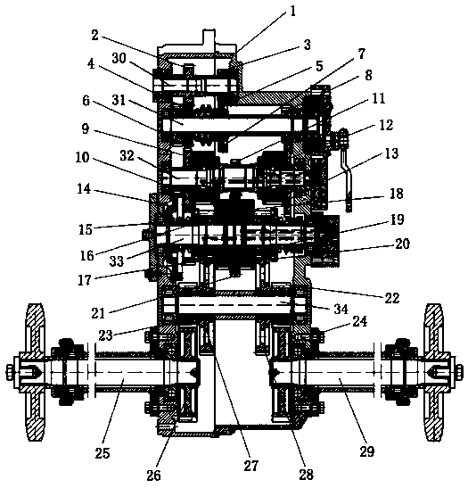
Continuously variable transmission adopting hydraulic control and flexible steering
A continuously variable transmission, hydraulic control system technology, applied in transmission control, gear transmission, multi-way valve, etc., can solve the problems of broken shaft, damaged steering gear, and high load requirements
- Summary
- Abstract
- Description
- Claims
- Application Information
AI Technical Summary
Problems solved by technology
Method used
Image

Examples
Embodiment 1
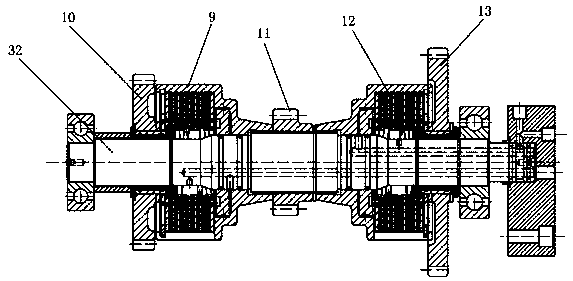
[0050] Going straight: the small holes in the oil passages of the first steering shaft and the second steering shaft do not emit oil, the friction plates of the first friction clutch and the second friction clutch are loosened, and are in a natural state, and the teeth of gear M and gear L are engaged.
[0051]
Embodiment 2
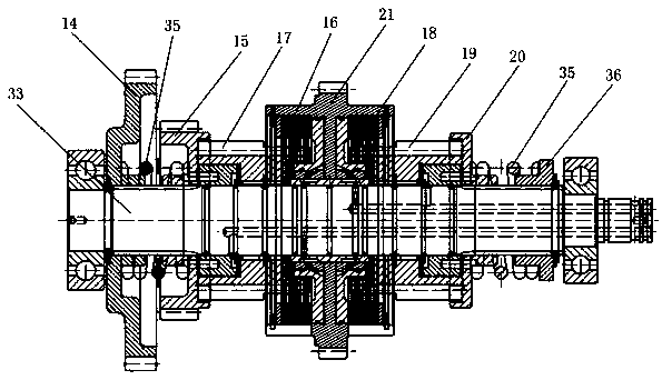
[0053] Left reverse and right positive: the friction plate of the first friction clutch of the steering axis is loosened, the friction plate of the second friction clutch is pressed, the friction plate of the third friction clutch of the second steering axis is pressed, and the friction plate of the fourth friction clutch is loosened , the gear M is disengaged and moves to the left, and the gear L is locked in place and does not move.
[0054]
Embodiment 3
[0056] The left is positive and the right is slow: the friction plate of the first friction clutch of the steering axis is pressed tightly, the friction plate of the second friction clutch is pressed and released, the friction plate of the third friction clutch of the second steering axis is loosened, and the friction plate of the fourth friction clutch is released. The friction discs are pressed tightly, the gear M's cogging engagement remains in place, and the gear L's cogging is disengaged and moves to the right.
[0057]
PUM
 Abstract
Description
Claims
Application Information