
Rotating type faucet valve element

A faucet valve, rotary technology, applied in the direction of sliding valve, valve device, engine components, etc., can solve the problems of shortening the service life of the quick-opening faucet valve core, the multi-inner diameter space of the valve core sleeve, and reducing the wall thickness of the valve core sleeve, etc. Achieve the effect of simple structure, improved structural strength and extended service life

Inactive Publication Date: 2019-04-19
徐少平
View PDF0 Cites 0 Cited by
  • Summary
  • Abstract
  • Description
  • Claims
  • Application Information

AI Technical Summary

Problems solved by technology

However, the water output of the faucet is determined by the aperture size of the through hole of the moving and fixed ceramic plates of the faucet valve core, and the size of the through hole is determined by the width and structure of the moving and fixed ceramic plates. In this way, in order to ensure the water output of the faucet Generally, if the width of the moving and fixed tiles is set to be larger, then the moving and fixed tiles need to occupy more inner diameter space of the valve core sleeve when installed in the valve core sleeve, and the outer diameter of the valve core sleeve does not increase. Under the premise, the wall thickness of the spool sleeve can only be reduced, thereby reducing the strength of the spool sleeve, making the threaded section of the spool sleeve prone to breakage under the action of installation stress and water pressure impact, shortening the quick opening Service life of faucet spool

Method used


Image

  • Rotating type faucet valve element

Examples


Embodiment 1

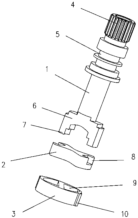
[0010] A rotary faucet spool described in Embodiment 1, such as figure 1 As shown, it includes a rotating screw rod 1, a moving ceramic piece 2 connected with the rotating screw rod and driven to rotate, and a static ceramic piece 3 cooperating with the moving ceramic piece; There are two sealing grooves 5 under the head and used to install the sealing ring, and the adapter 6 located at the bottom of the rotating screw; the inner side of the bottom of the adapter is provided with a boss 7 with a two-level stepped structure, and the moving ceramic plate is provided with an installation card that cooperates with the boss The bayonet 8 that connects, the both sides of static porcelain plate are provided with two water guide holes 9 that realize water channel conduction or sealing when moving ceramic plate rotates, and the plane area of ​​two water guide holes is four times of the plane area of ​​static porcelain plate three thirds.

[0011] In this embodiment, clip strips 10 pro...


PUM


Abstract

The invention discloses a rotating type faucet valve element. The valve element comprises a rotating screw rod, a movable ceramic chip connected with the rotating screw rod and driven to rotate, and afixed ceramic chip matched with the movable ceramic chip for mounting; the top of the rotating screw rod is provided with a rotating head with anti-sliding grains, two seal grooves arranged below therotating head and used for mounting seal rings, and an adapter arranged on the bottom of the rotating screw rod, a boss of a two-stage step structure is arranged on the inner side of the bottom of the adapter, a clamping opening matched with the boss for mounting and clamping is formed in the movable ceramic chip, the two sides of the fixed ceramic chip are provided with two water guide holes capable of achieving communicating or closing of a water channel when the movable ceramic chip rotates, and the plane area of the two water guide holes is 3 / 4 of the plane area of the fixed ceramic chip.The rapid water outlet effect is achieved only by slightly rotating the valve element by the small angle, the enough water outlet amount can be ensured when the valve element is not opened and closedexcessively, and water outlet is stable and smooth.

Description

technical field [0001] The invention relates to the structural field of valve cores, in particular to a rotary faucet valve core. Background technique [0002] At present, the spool on the market is installed in the faucet to control the water flow switch and the flow rate. The spools used for faucets include hemispherical valves, gate valves, etc. These two types of spools are relatively traditional and the most popular. The hemispherical valves can be switched to control fluid flow and Closing, while the gate valve controls the fluid flow and closing by moving up and down. There are also some water channels that are opened and closed with the fixed porcelain piece by rotating the moving piece. Since the fixed piece is provided with a through hole that communicates with the water inlet of the water inlet chamber of the faucet, the moving piece is provided with a The through holes communicated with the through holes of the faucet outlet chamber and the fixed porcelain plat...

Claims


Application Information

Patent Timeline
IPC IPC(8): F16K3/08F16K3/314
CPCF16K3/085F16K3/314
Inventor 徐少平
Owner 徐少平
Learn More