Laterally-arranged heat pump clothes drying cabinet of deep dehumidification device

A technology of equipment side and dry closet, which is applied in household dryers, washing devices, textiles and papermaking, etc., which can solve the problem of decreased evaporating heat absorption capacity and dehumidification capacity of evaporators, high power consumption of compressors, condensing pressure and evaporating pressure. The problems such as large difference can be solved, and the effect of improving the working condition of the compressor, increasing the dehumidification energy efficiency ratio, and expanding the cooling range

Active Publication Date: 2015-04-22
广州万二二麦工程技术有限公司
View PDF6 Cites 11 Cited by
  • Summary
  • Abstract
  • Description
  • Claims
  • Application Information

AI Technical Summary

Problems solved by technology

[0010] The pressure difference between the condensation pressure and the evaporation pressure of such a refrigeration and dehumidification system is too large, the power consumption of the compressor is too large, the compression ratio is too high, and the energy efficiency ratio is too low. Such working conditions are not safe!
[0011] 2. The integral condenser weakens the "supercooling" degree of the refrigerant liquid at the end of the condenser, resulting in a decrease in the evaporation and heat absorption capacity of the evaporator including the dehumidification capacity
However, a small amount of liquid refrigerant evaporates and vaporizes in the capillary in advance without entering the evaporator, which further reduces the evaporation and heat absorption capacity of the evaporator, including the dehumidification capacity.
[0015] 3. In the dry area, the air is evenly distributed and evenly flowed, etc.
[0017] However, for the heat pump dry wardrobe, how to solve the problem of uniform distribution and flow of air in the main space area of ​​the wardrobe, that is, the dry area, that is, how to make the dry air output from the refrigeration and dehumidification equipment room flow evenly through the horizontal section of the wardrobe and with the wet clothes? The problem of effective heat exchange without leaving dead ends has not been well resolved
[0018] Also, how to solve the problem of clogging the fin gaps of the evaporator and condenser in the refrigeration and dehumidification system caused by the lint falling off the clothes during the drying process and adhering to the air inlet of the evaporator and condenser during the cycle; How to solve the problem of natural discharge of the condensed water precipitated by the evaporator of the refrigeration and dehumidification system to cool and dehumidify the humid air by using the space height difference; there has been no effective solution to these problems

Method used


Image

  • Laterally-arranged heat pump clothes drying cabinet of deep dehumidification device
  • Laterally-arranged heat pump clothes drying cabinet of deep dehumidification device
  • Laterally-arranged heat pump clothes drying cabinet of deep dehumidification device

Examples


Embodiment 1

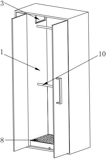
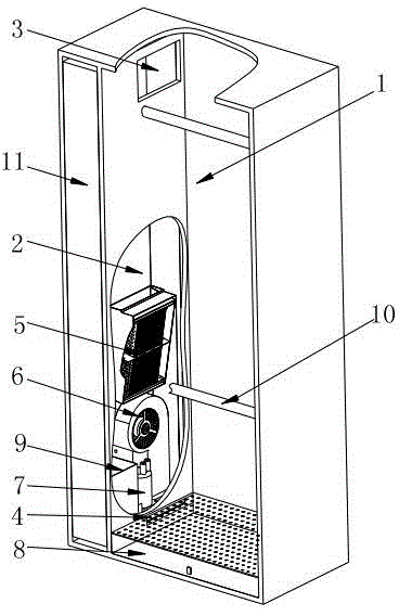
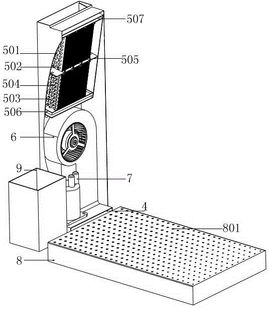
[0072] refer to Figure 1-8 , the present invention provides a heat pump dry closet with deep dehumidification equipment installed sideways, which is composed of a drying room 1 and an equipment room 2. A refrigeration and dehumidification device is installed in the equipment room 2, and the clothes to be dried are hung on the clothes rail of the drying room 1. 10 above; a closed-circuit air circulation is formed between the drying room 1 and the equipment room 2. The humid air in the drying room 1 is cooled and dehumidified by the refrigeration dehumidification device and heated to obtain dry air, and then transported to the drying room 1 to dry the clothes. dry.

[0073] Specifically, the shell of the dry closet can be made of wooden wall panels, steel-wood wall panels, or polyurethane foam and other thermal insulation materials to form thermal insulation wall panels, which are not limited here. like figure 2 As shown in , the entire drying cabinet is divided into a dryin...

Embodiment 2

[0098] The present invention also provides a heat pump dry closet installed on the side of the dehumidification system, including a drying room 1 and an equipment room 2 arranged on the side of the drying room 1. A refrigeration and dehumidification device is installed in the equipment room 2, and the specific structural form of the refrigeration and dehumidification device The refrigeration and dehumidification device described in Embodiment 1 can be used, and can also be designed according to specific conditions, which is not limited here. Between the upper and lower ends of the drying room 1 and the equipment room 2, there are an air inlet 3 and an air outlet 4 in the equipment room, wherein the air inlet 3 can be located at the upper end, and the air outlet 4 can be located at the lower end, or the air outlet 4 can be located at the upper end, and the air inlet can be located at the upper end. 3 is located at the end, which is not limited here. The air inlet 3 is located a...


PUM


Abstract

The invention provides a laterally-arranged heat pump clothes drying cabinet of a deep dehumidification device. The laterally-arranged heat pump clothes drying cabinet comprises a drying room and a refrigeration and dehumidification device. The refrigeration and dehumidification device is arranged on the side face of the drying room to form a high-position air suction and low-position air exhaust mode or a low-position air suction and high-position air exhaust mode. The drying room air inlet is provided with an air bag, and drying air flows into the drying room through through-holes formed in the air bag. The refrigeration and dehumidification device comprises a first condenser, a second condenser, a third condenser and an evaporator, wherein wet air is divided into two ways, one way of wet air flows through the first condenser and the second condenser to perform heating and temperature rise so as to obtain high-temperature drying air, the other way of wet air flows through the evaporator to perform temperature reduction and passes through the third condenser to perform heating and temperature rise so as to obtain high-temperature drying air, and two ways of drying air are input into the drying room after being mixed. By means of the refrigeration and dehumidification device, the problem that condensation pressure and condensation temperature of a traditional heat pump clothes drying machine at a speed-reduction drying phase are continuously improved, accordingly power consumption, pressure difference and compression ratio of a compressor are improved, energy efficiency ratio is reduced, the working condition is severely worsened, and even the compressor is burned down is solved.

Description

technical field [0001] The invention relates to the technical field of dry closet design, in particular to a heat pump dry closet with a dehumidification system installed on the side and with low condensation pressure, deep supercooling and deep dehumidification. Background technique [0002] The energy-saving characteristics of heat pumps make them widely used in heating, hot water, drying and other fields. Among them, the drying of wet materials requires a huge amount of heat, which is a large energy consumer. When heating and drying wet materials, a large amount of low-grade hot and humid air is produced after the drying operation. If heat pump technology can be used to recover the heat and humidity of these low-grade hot and humid air, it will not only save a huge amount of energy, but also reduce the The pollution of hot and humid air to the environment has important economic value and environmental significance. [0003] Most of the existing heat pump dryers are base...

Claims


Application Information

Patent Timeline
Patent Type & Authority Applications(China)
IPC IPC(8): D06F58/10D06F58/20D06F58/24
CPCD06F58/10D06F58/206D06F58/24
Inventor 薛世山李成伟王亮马骥刘玉恩王庆伦
Owner 广州万二二麦工程技术有限公司
Why Eureka
Try Eureka