A waste heat-driven double evaporator injection refrigeration system for refrigerated vehicles

A dual evaporator and refrigeration system technology, which is applied in the field of refrigerated vehicle waste heat-driven dual evaporator jet refrigeration system, can solve the problem that it is difficult to realize the deep cooling of refrigerated vehicle cab in summer at 0°C and below.

Active Publication Date: 2016-08-17
浙江氢阳电池有限公司
View PDF5 Cites 3 Cited by
  • Summary
  • Abstract
  • Description
  • Claims
  • Application Information

AI Technical Summary

Problems solved by technology

[0004] The purpose of the present invention is to solve the problem that the traditional jet refrigeration system is difficult to achieve deep cooling at 0°C and below, and the cab of the refrigerated truck is cooled in summer and heated in winter, and a jet refrigeration system with double evaporators driven by waste heat of the refrigerated truck is proposed

Method used


Image

  • A waste heat-driven double evaporator injection refrigeration system for refrigerated vehicles
  • A waste heat-driven double evaporator injection refrigeration system for refrigerated vehicles
  • A waste heat-driven double evaporator injection refrigeration system for refrigerated vehicles

Examples


Embodiment 1

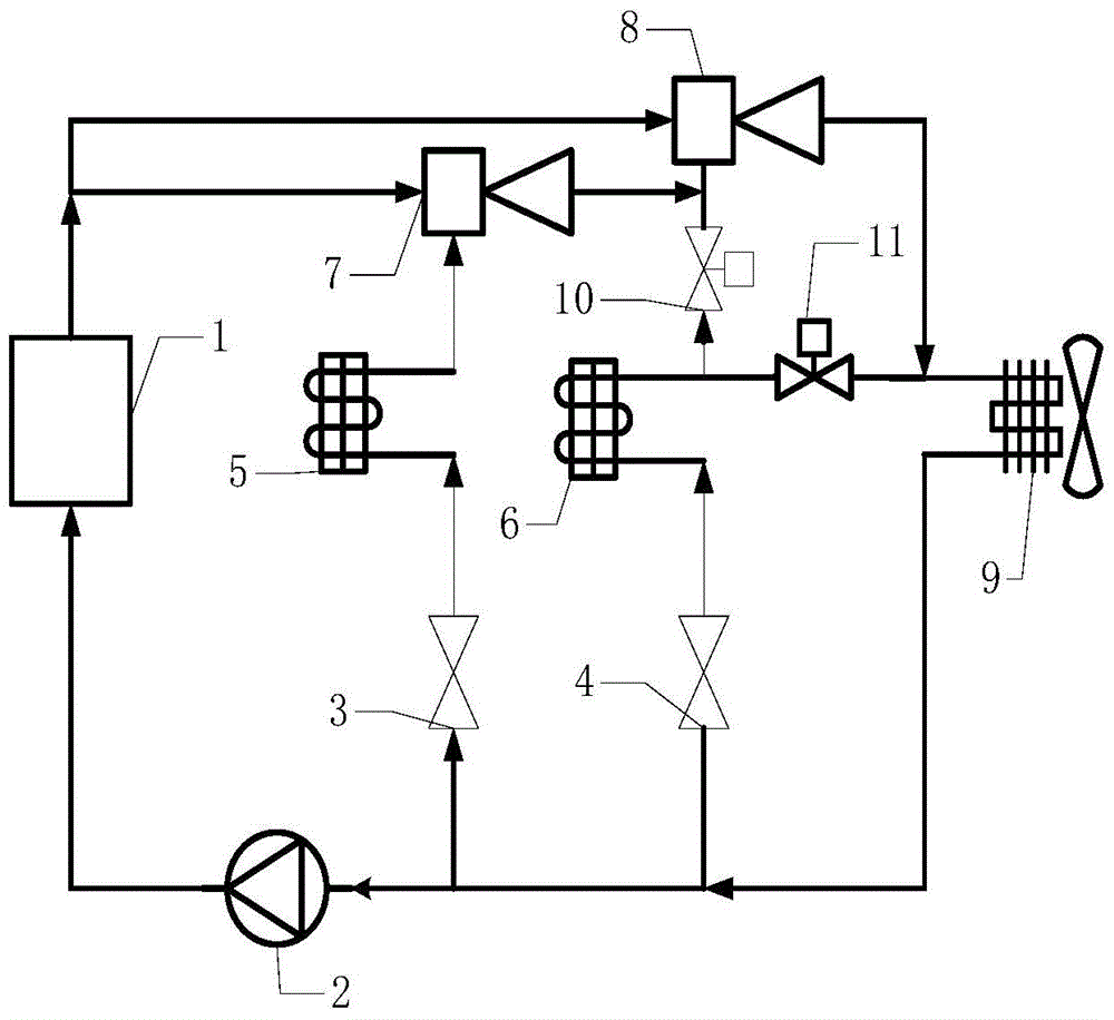
[0030] like figure 1 As shown, a waste heat-driven double evaporator jet refrigeration system for a refrigerated vehicle includes a waste heat recovery device 1, a circulation pump 2, a first throttling device 3, a second throttling device 4, a first evaporator 5, a second evaporator 6, the first ejector 7, the second ejector 8, the condenser 9, the first control valve 10 and the second control valve 11, the outlet end of the waste heat recovery device 1 is connected with the inlet end of the first ejector 7 and the second ejector respectively. The inlet end of the second ejector 8 is connected, the inlet end of the waste heat recovery device 1 is connected with the outlet end of the circulation pump 2, the outlet end of the first evaporator 5 is connected with the inlet end of the injection fluid of the first ejector 7, and the first evaporator The inlet port of the device 5 is connected with the outlet port of the first throttling device 3, the outlet port of the second evap...

Embodiment 2

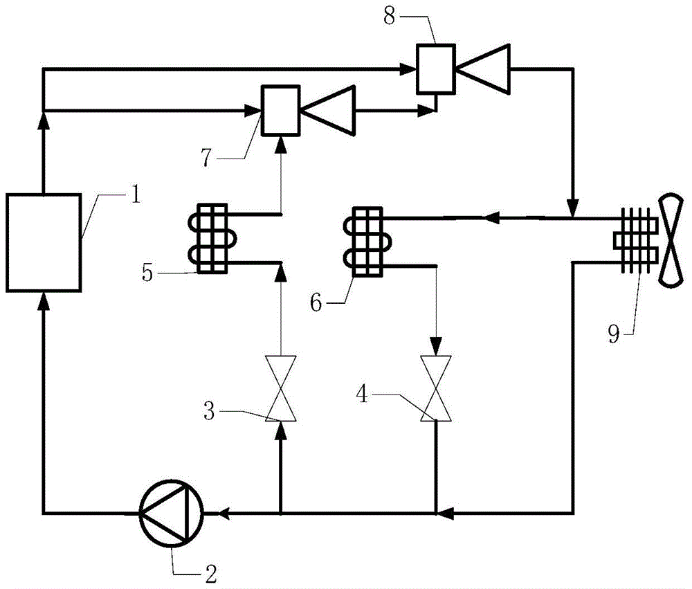
[0036] like Figure 4 As shown, a refrigerated vehicle waste heat-driven double evaporator jet refrigeration system includes a vehicle waste heat recovery device 1, a circulation pump 2, a first throttling device 3, a second throttling device 4, a first evaporator 5, a second The evaporator 6, the first ejector 7, the second ejector 8, the condenser 9, the four-way reversing valve 12, the outlet port of the automobile waste heat recovery device 1 are respectively connected with the working fluid inlet port of the first ejector 7 and the second ejector The working fluid inlet port of the injector 8 is connected, the inlet port of the automobile waste heat recovery device 1 is connected with the outlet port of the circulation pump 2, the outlet port of the first evaporator 5 is connected with the injection fluid inlet port of the first ejector 7, and the second The inlet end of the first evaporator 5 is connected with the outlet end of the first throttling device 3, the outlet e...


PUM


Abstract

The invention relates to a jet refrigeration system driven by waste heat of a refrigerated vehicle with double evaporators, comprising a waste heat recovery device, a circulation pump, a first throttling device, a second throttling device, a first evaporator, a second evaporator, a first jet device, second ejector, condenser, and gas flow control device; the first ejector and the second ejector inject refrigerants of different temperatures from the first evaporator and the second evaporator respectively; the refrigerant in the first evaporator The temperature of the refrigerant in the second evaporator can be controlled above zero, which is used for the summer cooling of the cab of the refrigerated truck; through the control of the gas flow control device, the refrigeration in the second evaporator can be changed. The temperature and flow direction of the agent can be used to realize the heating of the cab of the refrigerated truck in winter. The invention can make full use of the waste heat of the automobile to realize the whole process of refrigerating the refrigerated vehicle, and at the same time meet the air-conditioning requirements of the driver's cab, thereby broadening the application field of the jet refrigeration system.

Description

technical field [0001] The invention specifically relates to a spray refrigeration system with double evaporators driven by waste heat of a refrigerated vehicle. Background technique [0002] As people's pursuit of quality of life is getting higher and higher, the demand for fresh fruits, vegetables, meat, fish and egg milk with high nutritional value is increasing, which greatly promotes the development of refrigerated logistics. The refrigeration system of traditional refrigerated trucks operates by consuming fuel oil. The refrigeration process consumes a lot of energy, and at the same time increases the emission of vehicle exhaust and aggravates environmental pollution. Therefore, under the current situation of energy shortage and environmental pollution, it is urgent to solve the current The cooling method of refrigerated trucks has been improved. [0003] The jet refrigeration system uses low-grade heat sources such as solar energy and waste heat for refrigeration. It ...

Claims


Application Information

Patent Timeline
Patent Type & Authority Patents(China)
IPC IPC(8): F25B5/02F25B27/02F25B41/04B60H1/00F25B41/20F25B41/30
CPCF25B5/02F25B27/02B60H1/3232F25B41/20Y02A30/274
Inventor 王雷赵红霞丁兆秋
Owner 浙江氢阳电池有限公司
Why Eureka
Try Eureka