Waste-heat-drive drainage and injection type refrigerating system for refrigerator car

A refrigeration system and heat-driven technology, applied in refrigerators, refrigeration components, refrigeration and liquefaction, etc., can solve the problems of energy consumption, increased vehicle exhaust emissions, high evaporation pressure, etc., to reduce load, improve performance, and increase injection coefficient big effect

Active Publication Date: 2016-05-04
嘉兴索科能源科技有限公司
View PDF8 Cites 3 Cited by
  • Summary
  • Abstract
  • Description
  • Claims
  • Application Information

AI Technical Summary

Problems solved by technology

The refrigeration system of traditional refrigerated trucks operates by consuming fuel oil. The refrigeration process consumes a lot of energy, and at the same time increases the emission of vehicle exhaust and aggravates environmental pollution. Therefore, under the current situation of energy shortage and environmental pollution, it is urgent to solve the current Refrigerated truck refrigeration method is improved
[0003] The ejector refrigeration system uses low-grade heat sources such as solar energy and waste heat for refrigeration. It is a very promising way to save energy and reduce emissions by using the waste heat generated by automobiles to realize the refrigeration of refrigerated vehicles. However, the evaporation pressure generated by the traditional ejector refrigeration system is relatively high, so The traditional jet refrigeration system can only achieve refrigeration at 5°C and above, and it is difficult to achieve refrigeration and freezing refrigeration below 0°C, which also limits the application of jet refrigeration systems in the entire cold chain logistics

Method used


Image

  • Waste-heat-drive drainage and injection type refrigerating system for refrigerator car
  • Waste-heat-drive drainage and injection type refrigerating system for refrigerator car

Examples


Embodiment Construction

[0022] The present invention will be further described below in conjunction with the accompanying drawings and embodiments.

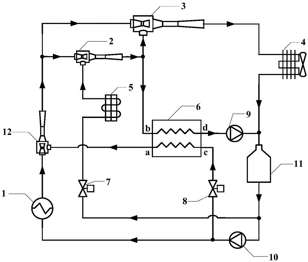
[0023] Such as figure 1 As shown, a refrigerated vehicle waste heat-driven diversion jet refrigeration system includes vehicle waste heat recovery device 1, injector I2, injector II3, condenser 4, evaporator 5, heat exchanger 6, expansion valve I7, expansion valve II8, circulation pump I9, circulation pump II10, liquid storage tank 11, injector III12, the outlet of injector III12 is respectively connected with the working fluid inlet of injector I2 and the working fluid inlet of injector II3, and the working fluid inlet of injector III12 It is connected with the first end of the automobile waste heat recovery device 1, the injection fluid inlet of the injector III12 is connected with the a end of the heat exchanger 6, the second end of the automobile waste heat recovery device 1 is connected with the first end of the circulation pump II10, the expansion...


PUM


Abstract

The invention discloses a waste-heat-drive drainage and injection type refrigerating system for a refrigerator car. The waste-heat-drive drainage and injection type refrigerating system comprises a car waste heat recovery device. Waste heat of the car waste heat recovery device passes through a first injector and enters secondary flow of a second injector. An output opening of the second injector is connected with a condenser. Meanwhile, a strand of fluid is led out from the secondary flow of the second injector and exchanges heat with the fluid led out from the condenser in a heat exchanger, so that the fluid led out from the secondary flow of the second injector is changed into a liquid state from a gas state. The liquid fluid is divided into three ways, wherein one way of fluid flows into the heat exchanger to exchange heat with the fluid led out from the secondary flow of the second injector and is changed into the gas state from the liquid state or changed into the gas-liquid two-phase state to flow into the car waste heat recovery device so as to preheat the car waste heat recovery device, another way of fluid flows into secondary flow of the first injector, and the third way of fluid flows into the car waste heat recovery device. By means of the waste-heat-drive drainage and injection type refrigerating system for the refrigerator car, refrigeration of the refrigerator car is achieved through waste heat drive of the car, no extra fuel needs to be consumed, and energy conservation of the refrigerator car is achieved.

Description

technical field [0001] The invention belongs to the technical field of ejectors, and relates to a waste heat-driven drainage ejector refrigeration system for a refrigerated vehicle. Background technique [0002] As people's pursuit of quality of life is getting higher and higher, the demand for fresh fruits, vegetables, meat, fish and egg milk with high nutritional value is increasing, which greatly promotes the development of refrigerated logistics. The refrigeration system of traditional refrigerated trucks operates by consuming fuel oil. The refrigeration process consumes a lot of energy, and at the same time increases the emission of vehicle exhaust and aggravates environmental pollution. Therefore, under the current situation of energy shortage and environmental pollution, it is urgent to solve the current The cooling method of refrigerated trucks has been improved. [0003] The jet refrigeration system uses low-grade heat sources such as solar energy and waste heat fo...

Claims


Application Information

Patent Timeline
Patent Type & Authority Applications(China)
IPC IPC(8): F25B27/02F25B41/00F25D19/00F25B41/40
CPCF25B27/02F25B41/00F25D19/003
Inventor 王雷丁兆秋赵红霞
Owner 嘉兴索科能源科技有限公司
Why Eureka
Try Eureka