Tilted-plated settlement pool

A technology of sloping plate sedimentation and sloping plate, applied in the direction of sedimentation tank, etc., can solve the problems such as affecting the effluent quality, unable to further improve the water production, and unable to reduce the inclination angle of 60°.

Inactive Publication Date: 2006-11-01
TONGJI UNIV +1
View PDF0 Cites 12 Cited by
  • Summary
  • Abstract
  • Description
  • Claims
  • Application Information

AI Technical Summary

Problems solved by technology

[0006] 1. The ascending direction of the countercurrent flow is opposite to the descending direction of the sludge, and there will be mud and water top flushing during work, which is a fatal shortcoming that the water production cannot be further improved
[0007] 2. The direction of the same direction flow and sludge slide is consistent, which not only eliminates the top impact on the sludge slide, but also helps to promote the sludge slide, but the collection of clean water

Method used


Image

  • Tilted-plated settlement pool
  • Tilted-plated settlement pool
  • Tilted-plated settlement pool

Examples


Embodiment Construction

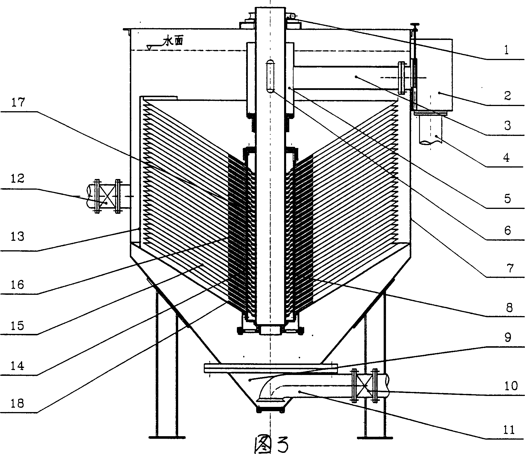
[0026] The present invention will be described in detail below in conjunction with the accompanying drawings.

[0027] As can be seen from Figure 3, the slanted plate sedimentation tank includes an outer cylinder 7 with a water inlet, a slant plate group 15 located in the outer cylinder, and a mud collection area 9 at the bottom of the outer cylinder, which is characterized in that the slanted plate sedimentation tank It also includes a transmission shaft and water outlet pipe 8 located at the center of the outer cylinder 7 and fixedly connected with the swash plate group 15, a transmission component 1 connected to the transmission shaft and water outlet pipe 8, and connected to the swash plate group 15 and the transmission shaft and water outlet pipe 8 water collection parts. Wherein the transmission part 1 is a motor and a worm gear transmission connected with the motor. The sloping plate group 15 is axially superimposed a plurality of rounded truncated slanted plates, the ...


PUM


Abstract

A tilted-plate precipitation pool for separating water from sludge is composed of an external cylindrical body, a group of tilted plates, a drive shaft arranged in the center, connected with said tilted plate group and used as water outlet tube, a driver unit and a water gathering unit. The rotating tilted plate group can drive water to form cyclone, so increasing the effect to separate water from sludge.

Description

Technical field: [0001] The invention relates to a settling device in the water treatment industry, in particular to a slant plate settling device which uses water flow to interact with settling tanks to accelerate solid-liquid separation and obtain ultra-high settling efficiency. Background technique: [0002] In the process of water purification, sediment is responsible for removing 80-90% of suspended solids, so its importance is self-evident. [0003] In recent years, the subsequent treatment process of precipitation - filtration, has made great progress in technology. New filter materials, such as microporous filter membranes, plastic fibers, plastic fine-groove discs, and wire mesh, have broken the dominance of quartz sand filter materials, making filter equipment more efficient and miniaturized. However, as the precipitating technology, since the success of inclined tube sedimentation and air flotation slag removal, there has been little progress in the past 20 years...

Claims


Application Information

Patent Timeline
IPC IPC(8): B01D21/02
Inventor 赵建夫张亚雷吴勇陈翼孙黄永宽崔程颖
Owner TONGJI UNIV
Why Eureka
Try Eureka