Laser ranger indoor calibration device and method based on fiber delay

A technology of laser range finder and optical fiber delay, applied in measuring devices, instruments, re-radiation of electromagnetic waves, etc., can solve problems such as large influence of weather and site

Pending Publication Date: 2019-04-19
HUAZHONG PHOTOELECTRIC TECH INST (CHINA SHIPBUILDING IND CORP THE NO 717 INST)
View PDF0 Cites 10 Cited by
  • Summary
  • Abstract
  • Description
  • Claims
  • Application Information

AI Technical Summary

Problems solved by technology

[0003] The first problem to be solved by the present invention is to provide an indoor calibration method and device that is not limited by the environment in view of the existing outdoor laser rangefinder calibration method, which is greatly affected by weather and venues;

Method used


Image

  • Laser ranger indoor calibration device and method based on fiber delay
  • Laser ranger indoor calibration device and method based on fiber delay
  • Laser ranger indoor calibration device and method based on fiber delay

Examples


Embodiment

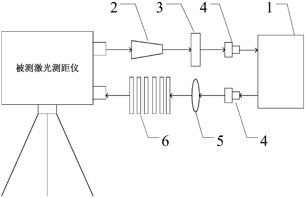
[0039] Such as figure 1 As shown in , when calibrating the maximum range of the laser rangefinder, the use of optical fiber to simulate the transmission of the laser is equivalent to mirror reflection. Since the effective receiving aperture of the laser rangefinder is much larger than the spot size emitted from the optical fiber, when the divergence angle of the laser beam When it is not greater than the receiving field of view, the ranging equation is:

[0040]

[0041] P rmin - minimum detectable power;

[0042] P t - the emission power of the laser;

[0043] K t ——The transmittance of the laser range finder’s transmitting optical system;

[0044] K r ——The transmittance of the receiving optical system of the laser range finder;

[0045] alpha 1 — Atmospheric attenuation coefficient during optical fiber extinction ratio test;

[0046] L 1 ——the total atmospheric distance from the laser range finder to the optical fiber delay device;

[0047] m 1 ——The attenuatio...


PUM


Abstract

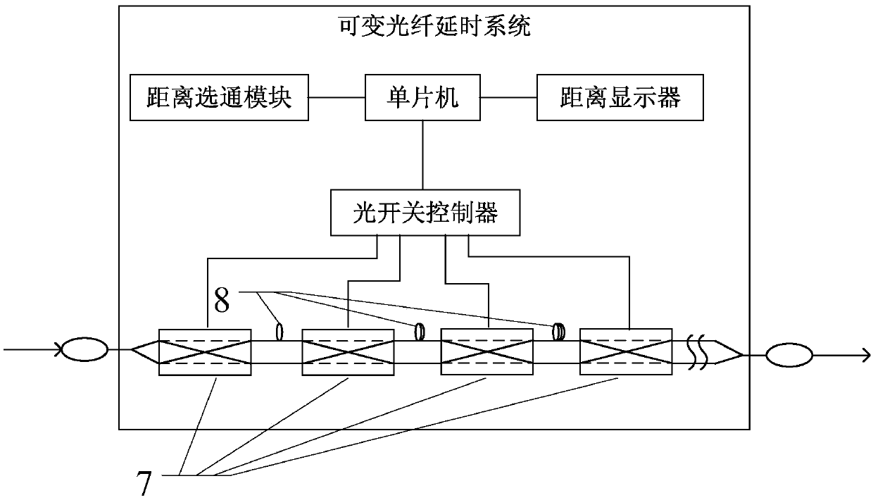
The invention discloses a laser ranger indoor calibration device and method based on fiber delay. The device herein comprises a receiving objective, a protective attenuator, a fiber coupler, a variable fiber delay system, a collimating objective, and a variable attenuator unit; the variable fiber delay system comprises a plurality of switches and a plurality of fiber rings different in length; thediameter of a laser beam emitted by a laser ranger under test is decreased through the receiving objective, the laser beam is then partly attenuated by the protective attenuator, the laser beam enters the variable fiber delay system from the fiber coupler and is subjected to delayed transmission, and after light path collimating is performed via the collimating objective and attenuating is performed via the variable attenuator unit, the laser beam returns to a receiving system of the laser ranger under test. The device and method herein are suitable for calibrating maximum ranging distance and ranging precision of a laser ranger.

Description

technical field [0001] The invention relates to the field of photoelectric ranging, in particular to an indoor calibration device and method for a laser range finder based on optical fiber time delay. Background technique [0002] The pulse laser rangefinder uses a pulse laser to emit laser pulses to the target, and calculates the distance to the target by measuring the time when the laser reaches the target and returns from the target to the receiving system of the rangefinder. The most important ranging performance of the pulse laser rangefinder is the maximum range and ranging accuracy. At present, the calibration methods for these two ranging performances are mainly divided into two categories: one is under the actual atmospheric environment conditions, with a certain The distance of the standard target plate is calibrated by the method of extinction ratio; the other is indoor simulation calibration. Under the actual atmospheric environment conditions, the whole test pr...

Claims


Application Information

Patent Timeline
Patent Type & Authority Applications(China)
IPC IPC(8): G01S7/497G01S17/08
CPCG01S7/497G01S17/08
Inventor 曹明朗王宇侯绿肖恒兵
Owner HUAZHONG PHOTOELECTRIC TECH INST (CHINA SHIPBUILDING IND CORP THE NO 717 INST)
Why Eureka
Try Eureka