
Optical cable capable of dissipating heat easily

An optical cable and optical fiber technology, applied in the field of easy heat dissipation optical cable, can solve the problems of data transmission interruption, increase of contact surface points, optical cable deformation, etc., to achieve the effect of facilitating heat dissipation, avoiding deformation, and increasing contact surface points

Active Publication Date: 2019-04-19
宏安集团有限公司 +2
View PDF10 Cites 4 Cited by
  • Summary
  • Abstract
  • Description
  • Claims
  • Application Information

AI Technical Summary

Problems solved by technology

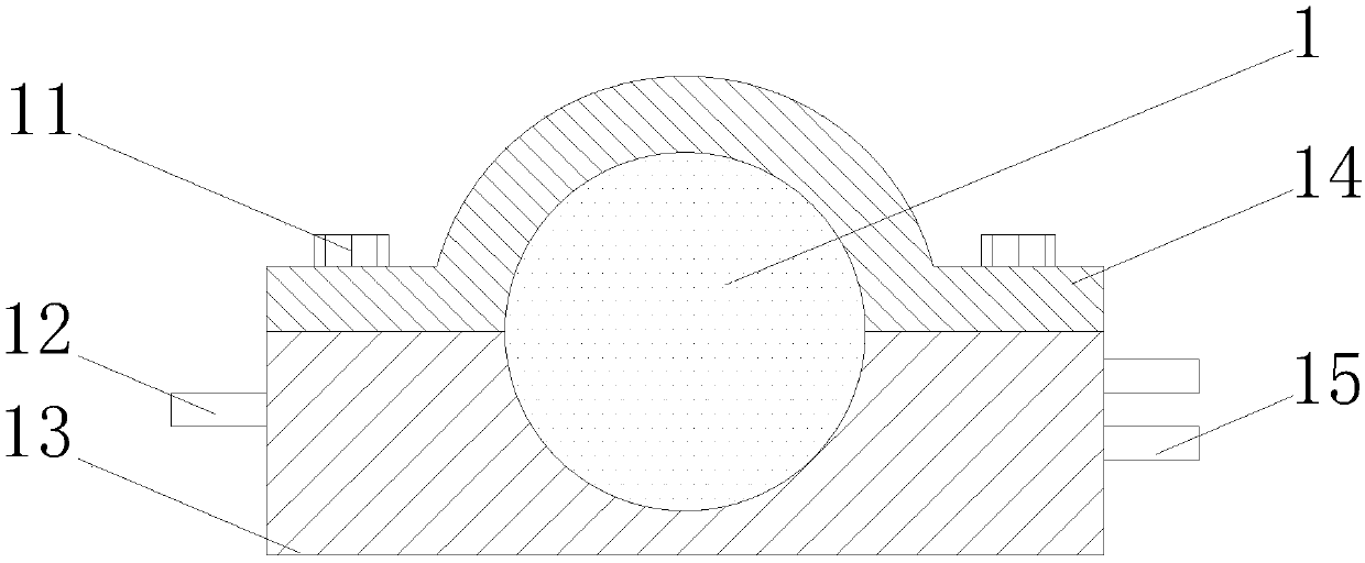
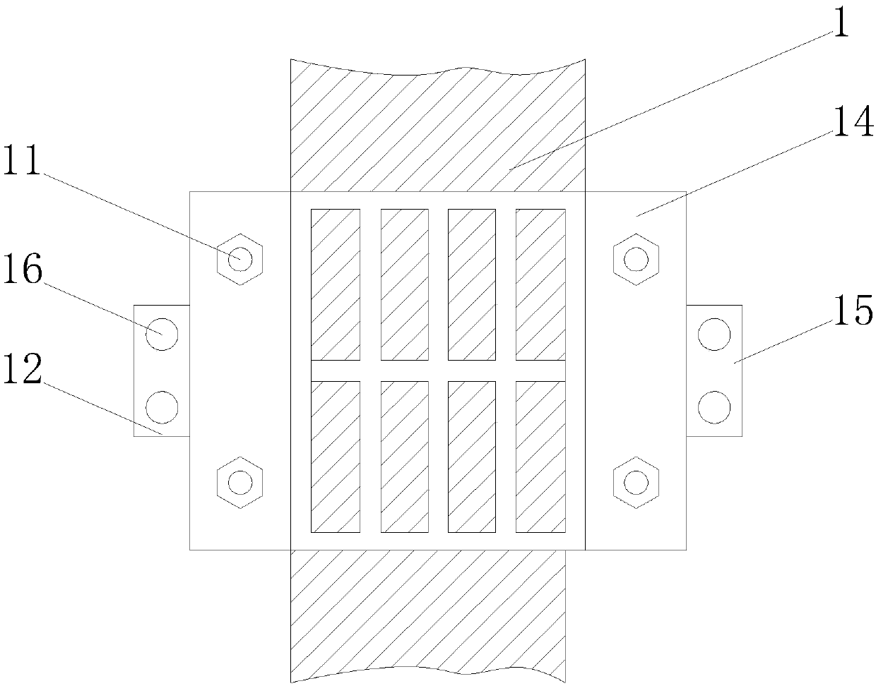
[0006] The object of the present invention is to provide a heat-dissipating optical cable in order to solve the above problems, by adding a thermal pad outside the optical fiber to transfer the heat generated inside the optical fiber to the outside of the optical fiber; With the combined use of the cable, it is avoided that the cable is ignited in the event of a fire, thereby destroying the cable and causing interruption of data transmission. , both the upper surface of the top plate and the lower surface of the bottom plate are set as a hollow structure formed by the intersection of multiple bone rods, and rubber pads are added on the inner surface of the bone rods to increase the contact surface between the top plate and the bottom plate point, and is conducive to the heat dissipation of the optical cable, then the top plate is fixed on the upper surface of the bottom plate with bolts, and the first connection plate of one connection structure is snapped between the two second connection plates of the other connection structure, and then Use bolts and nuts to pass through the through holes to fix them, so that multiple connection structures are connected in series, achieving the purpose of balancing multiple optical cables and avoiding deformation of optical cables

Method used


Image

  • Optical cable capable of dissipating heat easily
  • Optical cable capable of dissipating heat easily
  • Optical cable capable of dissipating heat easily

Examples


Embodiment Construction

[0022] The technical solutions in the embodiments of the present invention will be clearly and completely described below in conjunction with the accompanying drawings in the embodiments of the present invention. Obviously, the described embodiments are only a part of the embodiments of the present invention, rather than all the embodiments. Based on the embodiments of the present invention, all other embodiments obtained by those of ordinary skill in the art without creative work shall fall within the protection scope of the present invention.

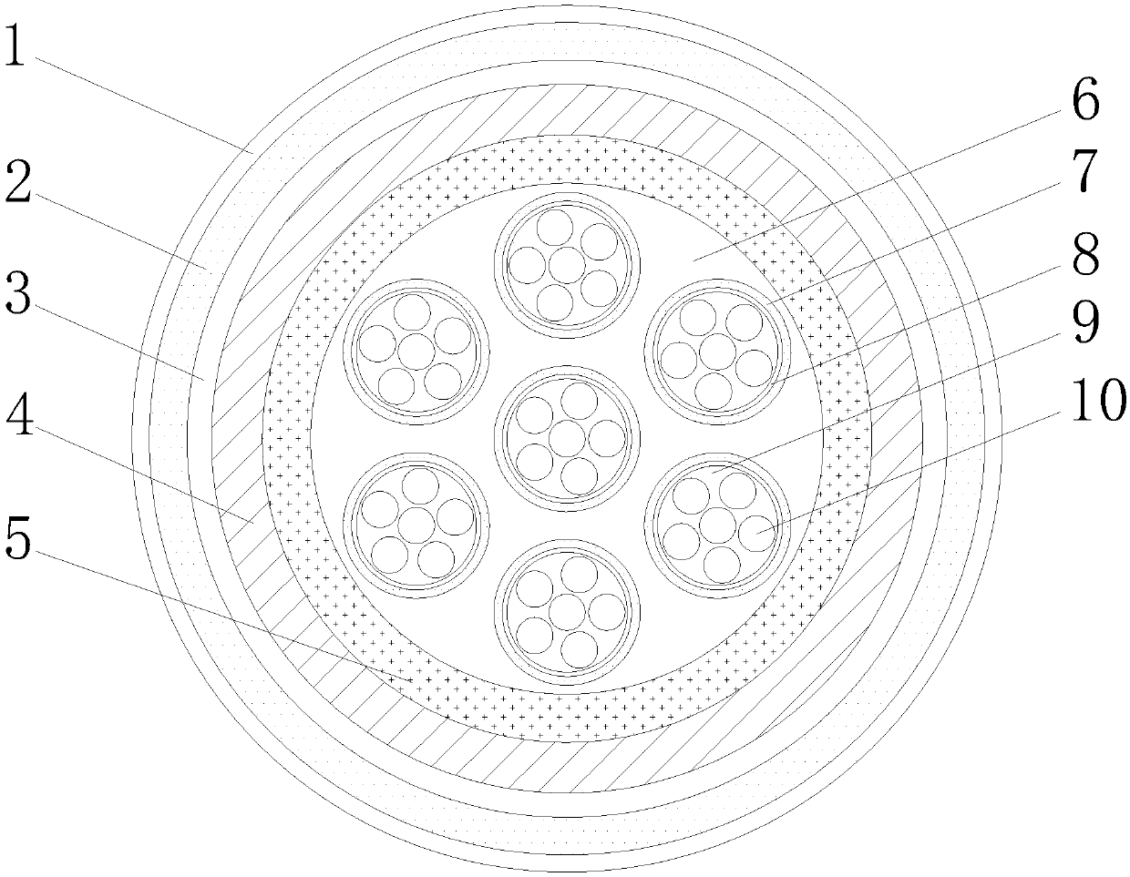
[0023] See Figure 1-3 As shown, a heat-dissipating optical cable includes an optical cable structure and a connecting structure that are sequentially installed from the inside to the outside; the optical cable structure includes a first fireproof layer 1, a second fireproof layer 3, a thermal pad 8 and an optical fiber 10. A thermally conductive pad 8 is sleeved on the outside of 10, an optical fiber paste 9 is filled between the optica...


PUM


Abstract

The invention belongs to the technical field of optical cables, in particular to an optical cable capable of dissipating heat easily. The optical cable comprises a first fire-proof layer, a polyethylene sheath, a second fire-proof layer, a water-blocking belt, a reinforced steel pipe, optical cable paste, loose sleeves, heat conduction pads, optical fiber paste, optical fibers, bolts, a first connecting plate, a bottom plate, a top plate, second connecting plates and through holes. Accordingly, heat generated in the optical fibers is transmitted to the exteriors of the optical fibers by additionally arranging the heat conduction pads outside the optical fibers; the phenomenon that the cable is ignited in case of fire, and data transmission is interrupted is avoided under cooperation of thefirst fire-proof layer, the second fire-proof layer and the reinforced steel pipe; when multiple optical cables are installed side by side, one cable is clamped in a circular groove between the bottom plate and the top plate, the top plate is fixed to the upper surface of the bottom plate through the bolts, and by means of cooperation of the first connecting plate and the second connecting plates, multiple connecting structures are connected in series, and then the purpose that multiple optical cables are balanced through mutual force is achieved.

Description

Technical field [0001] The invention belongs to the technical field of optical cables, and specifically is an optical cable with easy heat dissipation. Background technique [0002] Optical cable is manufactured to meet optical, mechanical or environmental performance specifications. It is a communication cable assembly that uses one or more optical fibers placed in a sheath as a transmission medium and can be used individually or in groups; It is mainly composed of optical fiber, plastic protective tube and plastic sheath. There is no metal such as gold, silver, copper and aluminum in the optical cable, and generally has no recycling value. Optical cable is composed of a certain number of optical fibers in a certain way to form a cable core, with a sheath outside. Some are also covered with an outer protective layer to realize a communication line for optical signal transmission. [0003] With the development of the times, optical fibers are used in more and more occasions. In so...

Claims


Application Information

Patent Timeline
Patent Type & Authority Applications(China)
IPC IPC(8): G02B6/44
CPCG02B6/443G02B6/4436G02B6/4439
Inventor 不公告发明人
Owner 宏安集团有限公司
Learn More