Heat sink flow control method, device and storage medium
A technology of flow control and heat sink, which is applied in the direction of flow control, flow control using electric devices, non-electric variable control, etc. It can solve the problems of insufficient heat removal capacity and low heat removal efficiency, and achieve the effect of improving capacity and meeting heat dissipation requirements
- Summary
- Abstract
- Description
- Claims
- Application Information
AI Technical Summary
Problems solved by technology
Method used
Image


Examples
Embodiment 1
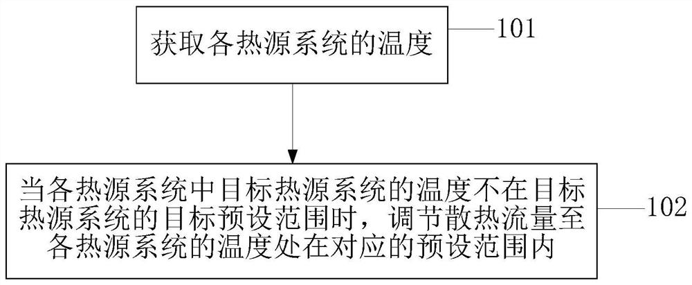
[0042] An embodiment of the present invention provides a heat sink flow control method, such as figure 1 As shown, the method includes:
[0043] Step 101, acquiring the temperature of each heat source system.
[0044] Each heat source system includes environmental control liquid cooling system, hydraulic system and engine lubricating oil system. The acquisition method is: collecting the temperature values of each system through the temperature sensors of each heat source system, and sending the temperature values to the computer for judgment.
[0045] Step 102, when the temperature of the target heat source system in each heat source system is not within the target preset range of the target heat source system, adjust the cooling flow until the temperature of each heat source system is within the corresponding preset range.
[0046] When the temperature of the target heat source system in each heat source system is within the target preset range of the target heat source...
Embodiment 2
[0069] An embodiment of the present invention provides a heat sink flow control method, such as figure 2 As shown, the method is applied to the fuel thermal management system, and the method includes:
[0070]Step 201. Detect whether an acceleration instruction is received.
[0071] Step 202: Increase the heat dissipation flow to the maximum value when an acceleration instruction is received.
[0072] Step 203, detecting whether an instruction to cancel the acceleration is received.
[0073] Step 204, when receiving the instruction to cancel the acceleration, acquire the temperature of each heat source system.
[0074] Step 205, when the temperature of the target heat source system is greater than the upper limit of the target preset range, increase the heat dissipation flow by a first preset amount.
[0075] Step 206: When the temperature of the target heat source system is lower than the lower limit of the target preset range, reduce the heat dissipation flow by a second...
Embodiment 3
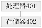
[0082] An embodiment of the present invention provides a heat sink flow control device, such as Figure 4 shown, including:
[0083] An acquisition module 301, configured to acquire the temperature of each heat source system;
[0084] An adjustment module 302, configured to adjust the cooling flow until the temperature of each heat source system is within the corresponding preset range when the temperature of the target heat source system in the various heat source systems is not within the target preset range of the target heat source system .
[0085] Further, the adjustment module 302 includes:
[0086] An increasing unit 3021, configured to increase the heat dissipation flow by a first preset amount when the temperature of the target heat source system is greater than the upper limit of the target preset range;
[0087] The reducing unit 3022 is configured to reduce the cooling flow by a second preset amount when the temperature of the target heat source system is lower...
PUM
 Abstract
Description
Claims
Application Information
 - R&D
- Intellectual Property
- Life Sciences
- Materials
- Tech Scout
- Unparalleled Data Quality
- Higher Quality Content
- 60% Fewer Hallucinations
Browse by: Latest US Patents, China's latest patents, Technical Efficacy Thesaurus, Application Domain, Technology Topic, Popular Technical Reports.
© 2025 PatSnap. All rights reserved.Legal|Privacy policy|Modern Slavery Act Transparency Statement|Sitemap|About US| Contact US: help@patsnap.com