Bridge emergency command and dispatch system and method based on two-dimensional and three-dimensional linkage
A technology for emergencies and bridges, which is applied in the field of bridge emergency command and dispatch systems based on 2D and 3D linkage, which can solve the problems of lack of 3D bridge models, inability to visually see bridge structures, and inability to efficiently utilize existing resources.
- Summary
- Abstract
- Description
- Claims
- Application Information
AI Technical Summary
Problems solved by technology
Method used
Image
Examples
specific Embodiment
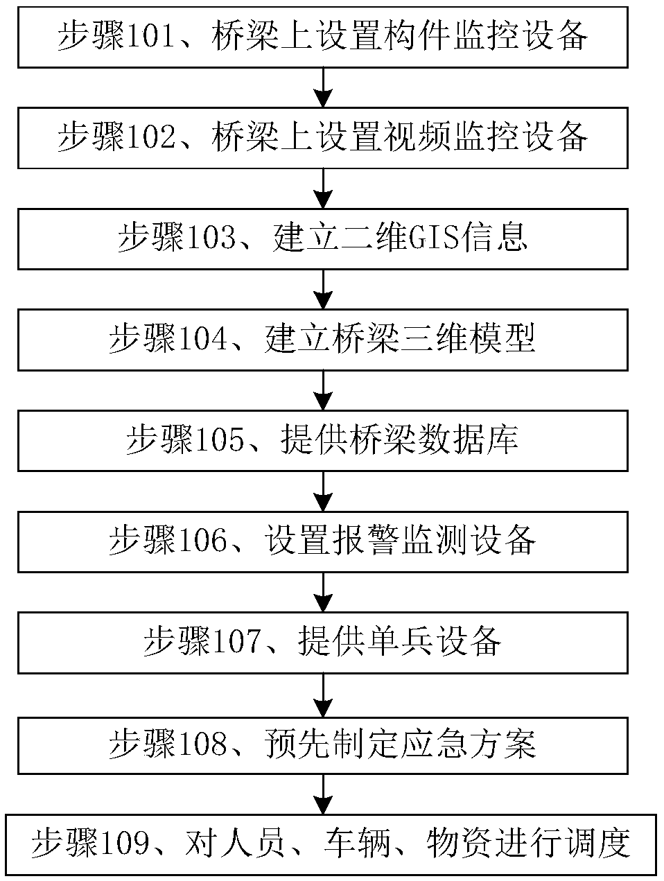
[0043] see figure 1 Shown is a specific embodiment of the command and dispatch method for bridge emergencies based on 2D and 3D linkage described in this application. The method includes:
[0044] Step 101, setting component monitoring equipment on the main girder span, arch ring, and bridge piers on the bridge, and the component monitoring equipment is used to collect real-time monitoring data;
[0045] Step 102, the upper and lower bridge entrances of the bridge, and the accident-prone points are provided with video monitoring equipment, and the video monitoring equipment is used to monitor the real-time road conditions of the bridge;
[0046] Step 103, establishing two-dimensional GIS information, including GIS maps, the real-time road conditions, and nearby fire hospital information layers;
[0047] Step 104: Establish a 3D model of the bridge, digitize the bridge, perform 3D fine modeling according to the components of the bridge, the components have a unique mark, perfo...
Embodiment 2
[0055] Another embodiment of the bridge emergency command and dispatch method based on 2D and 3D linkage described in this application, the method includes:
[0056] Step 201, setting component monitoring equipment on the main girder span, arch ring, and bridge piers on the bridge, and the component monitoring equipment is used to collect real-time monitoring data;
[0057] Step 202, the upper and lower bridge entrances and accident-prone points of the bridge are provided with video monitoring equipment, and the video monitoring equipment is used to monitor the real-time road conditions of the bridge;
[0058] Step 203, establishing two-dimensional GIS information, including GIS maps, the real-time road conditions, and information layers of nearby fire hospitals;
[0059] Step 204: Establish a 3D model of the bridge, digitize the bridge, perform 3D fine modeling according to the components of the bridge, the components have a unique mark, perform data connection with the compo...
Embodiment 3
[0067] see figure 2 Shown is a specific embodiment of the bridge emergency command and dispatch system based on 2D and 3D linkage described in this application. The system includes: component monitoring equipment 31, video monitoring equipment 32, alarm module 33, bridge 3D module 34, and 2D GIS Module 35, bridge database module 36, individual equipment 37, pre-plan module 38, control center module 39, scheduling module 40;
[0068] Step 301, the component monitoring device 31 is coupled with the bridge three-dimensional module 34 and the alarm module 33, and is used to collect real-time monitoring data and send it to the bridge three-dimensional module 34 and the alarm module 33;
[0069] Step 302, the video monitoring device 32 is coupled with the two-dimensional GIS module 35, used to collect real-time road conditions, and send to the two-dimensional GIS module 35;
[0070] Step 303, the individual equipment 37 is coupled with the control center module 39, and is used to ...
PUM
 Abstract
Description
Claims
Application Information
 - R&D
- Intellectual Property
- Life Sciences
- Materials
- Tech Scout
- Unparalleled Data Quality
- Higher Quality Content
- 60% Fewer Hallucinations
Browse by: Latest US Patents, China's latest patents, Technical Efficacy Thesaurus, Application Domain, Technology Topic, Popular Technical Reports.
© 2025 PatSnap. All rights reserved.Legal|Privacy policy|Modern Slavery Act Transparency Statement|Sitemap|About US| Contact US: help@patsnap.com


