Winding device

A winding device and winding core technology, which is applied in the direction of wire-wound capacitor machines, sustainable manufacturing/processing, electrochemical generators, etc., can solve the problem of quality reduction of winding components and achieve the effect of preventing deformation

Active Publication Date: 2019-04-19
CKD
View PDF10 Cites 2 Cited by
  • Summary
  • Abstract
  • Description
  • Claims
  • Application Information

AI Technical Summary

Problems solved by technology

[0004] However, there is some kind of defective part on the electrode sheet (for example, the seam between the sheets, etc.)
In this case, if the winding element includes the above-mentioned defective parts, there is a danger of causing the quality of the winding element to deteriorate.

Method used


Image

  • Winding device
  • Winding device
  • Winding device

Examples


no. 1 Embodiment approach

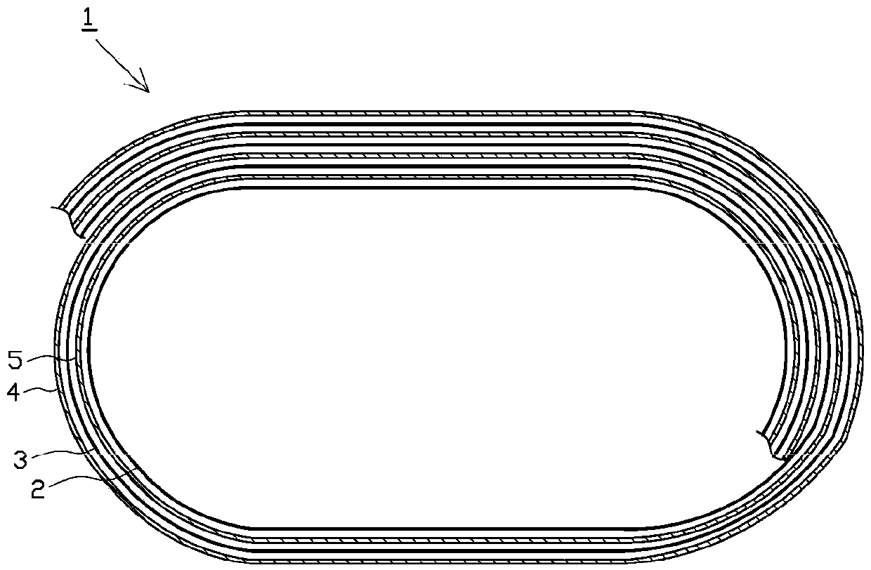
[0071] First, the structure of a lithium ion battery element as a wound element obtained by a winding device will be described.

[0072] picture figure 1 As shown, a lithium-ion battery 1 (hereinafter simply referred to as "battery element 1") is manufactured in such a way that a positive electrode sheet 4 and a negative electrode sheet 5 are overlapped via two separator sheets 2, 3. Status winding. In addition, instead of the two separators 2 and 3, one folded separator may be used. In addition, below, the separator sheets 2 and 3 and the electrode sheets 4 and 5 are referred to as "various sheets 2 to 5" for convenience of description.

[0073] The separators 2 and 3 are strip-shaped with the same width and made of an insulator such as polypropylene (PP) to prevent the electrode sheets 4 and 5 from contacting each other and short-circuiting.

[0074] The electrode sheets 4 and 5 are made of thin metal sheets and have substantially the same width as the separator sheets 2 ...

no. 2 Embodiment approach

[0184] Hereinafter, the second embodiment will be described focusing on the differences from the first embodiment described above.

[0185] In the above-mentioned first embodiment, the path maintaining mechanism is constituted by moving the moving mechanism 96 such as the defective winding core 924 . In contrast to this, in this second embodiment, like Figure 22 , Figure 23 As shown, the route-changing roller 97 provided along the transport route of the positive electrode sheet 4 constitutes the route maintaining mechanism. The path changing roller 97 is installed downstream of the electrode cutter 72 and upstream of the defective winding core 924 . The path changing roller 97 is formed of a freely rotatable roller (pulley). In the following, the path changing roller 97 provided in the positive electrode sheet supply mechanism 31 is described, but the same path changing roller 97 is also provided in the negative electrode sheet supply mechanism 41 .

[0186] The route ch...


PUM


Abstract

An object of the present invention is to provide a winding device which can reduce the size of an apparatus and suppress an increase in cost. The winding device includes: a sheet supply mechanism (71)that is disposed along a conveyance path of the object piece as at least one of the electrode sheet and the separator and is configured to switch holding and holding release of an object piece through the on-off motions of two holding portions (71a, 71b); an electrode cutter (72) arranged at the downstream of the sheet supply mechanism (71) and configured to cut off the object piece through the on-off motion of two blade portions (72a, 72b); and a defective take-up core (924) arranged at the downstream of the electrode cutter (72) and configured to wind one part of the object piece at the defective portion through the rotation itself. A path maintenance mechanism is employed to at least maintain the transmitting path corresponding to the sheet supply mechanism (71) and the electrode cutter (72) to a certain position even though the outer diameter of the winded object piece is changed in the winding of the object piece by the defective take-up core (924).

Description

technical field [0001] The present invention relates to, for example, a winding device for obtaining a wound element built into a secondary battery or the like. Background technique [0002] For example, a wound element for a secondary battery such as a lithium ion battery is manufactured in such a manner that a positive electrode sheet coated with a positive active material and a negative electrode sheet coated with a negative active material It is wound up in a superimposed state via a separator formed of an insulating material. [0003] In a winding device for manufacturing a wound element, two electrode sheets and a separator sheet supplied from a raw roll wound in a roll shape are conveyed to a winding core along respective conveying paths. In addition, the winding device includes: a cutting mechanism for cutting the electrode sheets provided corresponding to the respective routes of the conveying routes of the electrode sheets; Upstream of the mechanism, the electrod...

Claims


Application Information

Patent Timeline
Patent Type & Authority Applications(China)
IPC IPC(8): H01M10/0587H01G13/02
CPCH01M10/0587H01G13/02Y02E60/10Y02P70/50
Inventor 福原洋平
Owner CKD
Why Eureka
Try Eureka