Pipe welding robot

A welding robot and pipeline technology, applied in welding equipment, auxiliary welding equipment, welding/cutting auxiliary equipment, etc., can solve problems such as health damage and irritating gas generation, improve accuracy, improve stability, and avoid large angle errors Effect

Active Publication Date: 2019-04-23
HARBIN UNIV
View PDF12 Cites 21 Cited by
  • Summary
  • Abstract
  • Description
  • Claims
  • Application Information

AI Technical Summary

Problems solved by technology

[0002] Pipeline is one of the common transportation methods for fluids, which has the advantages of small footprint and low cost. For the existing welding robots, although the welding process does not require manual operation, it still requires manual monitoring of its welding status , while welding will produce irritating gas and intense light, monitoring personnel in this environment for a long time will easily cause irreversible damage to health

Method used


Image

  • Pipe welding robot
  • Pipe welding robot
  • Pipe welding robot

Examples


specific Embodiment approach 1

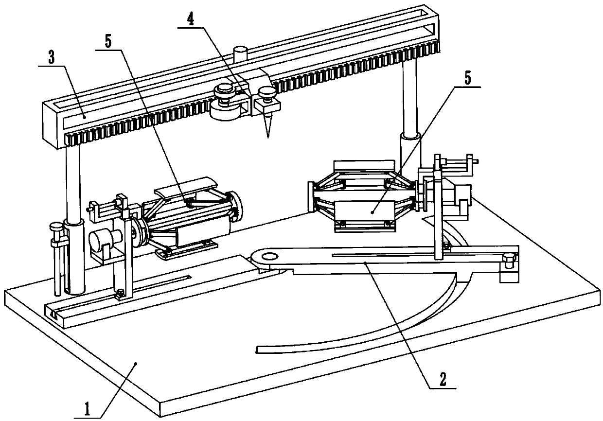
[0019] Combine below Figure 1-5 Describe this embodiment, a pipe welding robot, including a base 1, an angle adjustment seat 2, a height adjustment assembly 3, a welding assembly 4 and a pipe fixing assembly 5, the right end of the base 1 is provided with an arc-shaped groove 1-1, One end of the angle adjustment seat 2 is fixedly connected to the left end of the base 1, and the other end of the angle adjustment seat 2 is slidably connected in the arc groove 1-1; the height adjustment component 3 is fixedly connected to the rear end of the base 1, and the welding component 4 is slidably connected On the upper end of the height adjustment assembly 3, there are two pipe fixing assemblies 5, and the two pipe fixing assemblies 5 are respectively slidably connected to the two ends of the angle adjustment seat 2. When the present invention is in use, the two pipeline fixing assemblies 5 are adjusted to a horizontal state, and at the same time, the two pipeline fixing assemblies 5 ar...

specific Embodiment approach 2

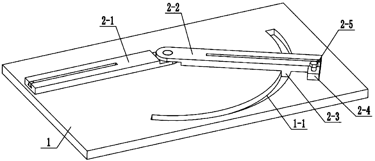
[0020] Combine below Figure 1-5 To illustrate this embodiment, the angle adjustment seat 2 includes a fixed base 2-1, a movable base 2-2, an arc slider 2-3, a screw seat plate 2-4 and a locking screw 2-5; the fixed base 2 -1 is fixedly connected to the left end of the base 1, the right end of the fixed base 2-1 is connected to one end of the movable base 2-2 through a hinge shaft, and the other end of the movable base 2-2 is fixedly connected to the sliding arc-shaped block 2-3, which is arc-shaped The slider 2-3 is slidably connected in the arc groove 1-1, the screw seat plate 2-4 is fixedly connected to the outer end of the movable base 2-2, and the screw seat plate 2-4 is threadedly connected to the locking screw 2-5 , the locking screw 2-5 is on the base 1; the top surfaces of the fixed base 2-1 and the movable base 2-2 are all provided with T-shaped chute; the outer end of the T-shaped chute is fixedly connected to the stopper . When the angle adjustment seat 2 is in u...

specific Embodiment approach 3

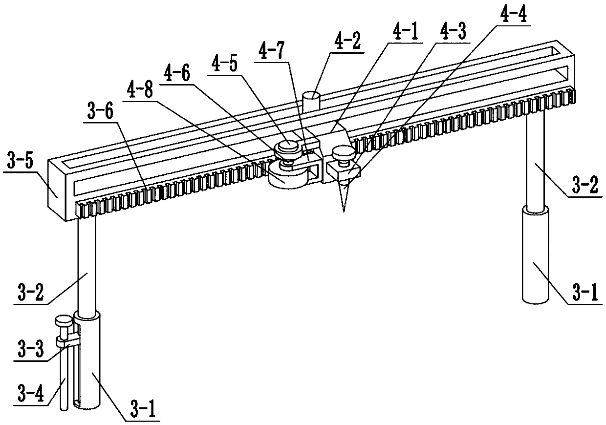
[0021] Combine below Figure 1-5Illustrating this embodiment, the height adjustment assembly 3 includes a sleeve rod 3-1, a telescopic rod 3-2, a limit block 3-3, an adjustment screw 3-4, a chute frame 3-5 and a rack 3-6 ; The two sleeve rods 3-1 are symmetrically and fixedly connected to the rear end of the base 1, and the lower ends of the two telescopic rods 3-2 are slidably connected in the two sleeve rods 3-1 respectively; the sleeve rod 3-1 at the left end is provided with The side chute, the limit block 3-3 is slidably connected in the side chute, the limit block 3-3 is fixedly connected to the lower end of the telescopic rod 3-2 at the left end, and the adjusting screw 3-4 is connected to the limit block 3 by threads -3, the lower end of the adjusting screw 3-4 is rotatably connected to the base 1 through the bearing with seat; the chute frame 3-5 is fixedly connected to the upper ends of the two telescopic rods 3-2; The middle end is provided with a horizontal chute,...


PUM


Abstract

The present invention relates to the field of welding equipment, in particularly to a pipe welding robot. The right end of a base is provided with an arc-shaped groove; one end of an angle adjusting seat is fixedly connected to the left end of the base; the other end of the angle adjusting seat is slidably connected to the inner side of the arc-shaped groove; a height adjusting component is fixedly connected to the rear end of the base; the welding component is slidably connected to the upper end of the height adjusting component; and two pipeline fixing components are slidably connected to both ends of the angle adjusting seat correspondingly. When the two pipeline fixing components are in the same horizontal plane, the 360 DEG all-round welding for two pipelines to be welded is achieved;and the position of the two pipelines to be welded is fixed, so that the stability of a to-be-welded part is greatly improved, and the to-be-welded part is prevented from shifting during the machining process to affect the machining quality; and the spot welding can be performed on a pipeline to be welded at different angles, so that the manual adjustment of the large angle error is avoided and the welding precision is improved.

Description

technical field [0001] The invention relates to the field of welding equipment, in particular to a pipeline welding robot. Background technique [0002] Pipeline is one of the common transportation methods for fluids, which has the advantages of small footprint and low cost. For the existing welding robots, although the welding process does not require manual operation, it still requires manual monitoring of its welding status , and irritating gas and intense light will be produced during welding, and monitoring personnel in this environment for a long time may cause irreversible damage to health. SUMMARY OF THE INVENTION [0003] The purpose of the present invention is to provide a pipe welding robot, the beneficial effect of which is that when the two pipe fixing assemblies in the present invention are on the same horizontal plane, the two pipes to be welded can realize 360° omni-directional welding, and the two pipes can be welded together. The position of the pipeline...

Claims


Application Information

Patent Timeline
Patent Type & Authority Applications(China)
IPC IPC(8): B23K37/053B23K37/02
Inventor 张峰
Owner HARBIN UNIV
Why Eureka
Try Eureka