Turnover tooling and turnover method

A technology of turning over work and tooling, which is applied in the field of mechanical tooling, and can solve problems such as large extrusion deformation and assembly misalignment

Active Publication Date: 2019-04-23
WUHAN MARINE MACHINERY PLANT
View PDF4 Cites 1 Cited by
  • Summary
  • Abstract
  • Description
  • Claims
  • Application Information

AI Technical Summary

Problems solved by technology

[0005] However, the support of wood boards or tires will cause large extrusion deformation of parts in contact with wood boards or tires, which will cause assembly misalignment

Method used


Image

  • Turnover tooling and turnover method
  • Turnover tooling and turnover method
  • Turnover tooling and turnover method

Examples


Embodiment Construction

[0046] In order to make the object, technical solution and advantages of the present invention clearer, the implementation manner of the present invention will be further described in detail below in conjunction with the accompanying drawings.

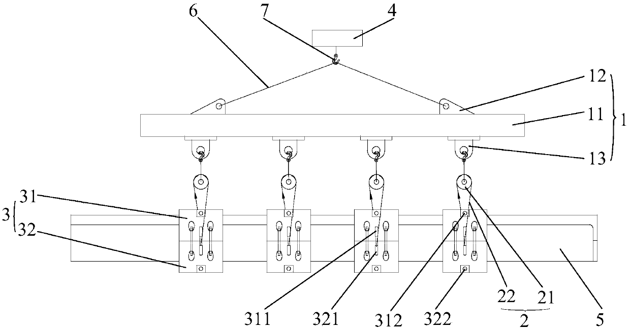
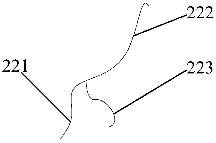
[0047] The embodiment of the present invention provides a turning tool, figure 1 For a structural schematic diagram of a stand-up frock provided by an embodiment of the present invention, see figure 1, in this embodiment, the stand-up tooling includes: a lifting unit 1, an overturning unit 2, and a locking unit 3; the lifting unit 1 is used for hoisting on the crane 4; the overturning unit 2 includes a fixed pulley 21 and a bifurcated sling 22, the fixed pulley 21 is connected with the lifting unit 1, the bifurcated sling 22 is wound on the fixed pulley 21, the bifurcated sling 22 includes a first main end 221, a second main end 222 and an auxiliary end 223, and the auxiliary end 223 is connected to the first main end 221 and the The ...


PUM


Abstract

The invention discloses a turnover tooling and a turnover method and belongs to the field of mechanical toolings. A lifting unit is connected with a travelling crane; each turnover unit comprises a fixed pulley and a forked sling, wherein the fixed pulley is connected with the lifting unit, and the forked sling is wound on the fixed pulley and comprises a first main end, a second main end and an auxiliary end; and upper locking blocks and lower locking blocks are detachably mounted together to form locking units correspondingly, clamping spaces used for clamping parts are formed between the upper locking blocks and the corresponding lower locking blocks, upper main lifting holes are formed in the two sides of an opening of each upper locking block correspondingly, lower main lifting holesare formed in the two sides of an opening of each lower locking block correspondingly, the two main ends of each forked sling are bound into the upper main lifting holes and the lower main lifting holes aligned with the upper main lifting holes of the corresponding locking unit, an upper auxiliary lifting hole is formed in each upper locking block, a lower auxiliary lifting hole is formed in eachlower locking block, the auxiliary end of each forked sling is bound into the corresponding upper auxiliary lifting hole or the corresponding lower auxiliary lifting hole, and the situation that whenparts are overturned, local stress is excessively large, the parts are deformed due to extrusion, and assembling of the parts is affected is avoided.

Description

technical field [0001] The invention belongs to the field of mechanical tooling, in particular to a turning tool and a turning method. Background technique [0002] Composite materials are one of the most popular materials in the manufacture of high-end, precision and cutting-edge devices in recent years. Among them, carbon fiber has the advantages of light weight, heat insulation and good sealing, and has been widely used in equipment, aviation, aerospace, navigation, etc. multiple fields. [0003] There is a waist-shaped half-pipe part, which is formed by carbon fiber layup. Its physical properties are very different from metal materials. It is a brittle material. When the local force is too large, it will even cause the fiber to break. There are a large number of counterbore holes drilled on both sides for post-assembly positioning. Because the parts are large, the parts need to be turned over during the post-assembly positioning. [0004] In the prior art, it is often ...

Claims


Application Information

Patent Timeline
Patent Type & Authority Applications(China)
IPC IPC(8): B66C1/18B66C13/08
CPCB66C1/18B66C13/08
Inventor 王充聪吴红琼董小亮
Owner WUHAN MARINE MACHINERY PLANT
Why Eureka
Try Eureka