Supercharge Your Innovation With Domain-Expert AI Agents!

Layered water-intake independent intake tower structure for high water head power station

A layered water intake, independent technology, used in hydropower stations, hydroelectric power generation, water conservancy projects, etc., can solve the problem that the accident maintenance gate cannot be remotely controlled, and the water inlet tower of a large-flow power station cannot be used for layered water intake, and the trash rack passes through. The problems such as the small area of ​​the grille can be achieved to achieve the effect of facilitating remote automatic control, convenient opening and closing operation, and increasing the area of ​​the trash grille.

Pending Publication Date: 2019-04-23
CHINA WATER RESOURCES BEIFANG INVESTIGATION DESIGN & RES
View PDF0 Cites 0 Cited by
  • Summary
  • Abstract
  • Description
  • Claims
  • Application Information

AI Technical Summary

Problems solved by technology

The disadvantage is that the area of ​​the trash rack passing through the grid is too small, and the loss of water head is large. It will greatly reduce the power generation efficiency when used in the water inlet tower of the power station. The downstream flow channel of the emergency maintenance gate cannot be closed in time in case of emergency. The emergency maintenance gate cannot be remotely controlled and cannot be used. Stratified Water Intake in Inlet Towers of Large Flow Power Stations

Method used


Image

  • Layered water-intake independent intake tower structure for high water head power station
  • Layered water-intake independent intake tower structure for high water head power station
  • Layered water-intake independent intake tower structure for high water head power station

Examples


Embodiment Construction

[0021] Below in conjunction with accompanying drawing and specific embodiment the present invention is described in further detail:

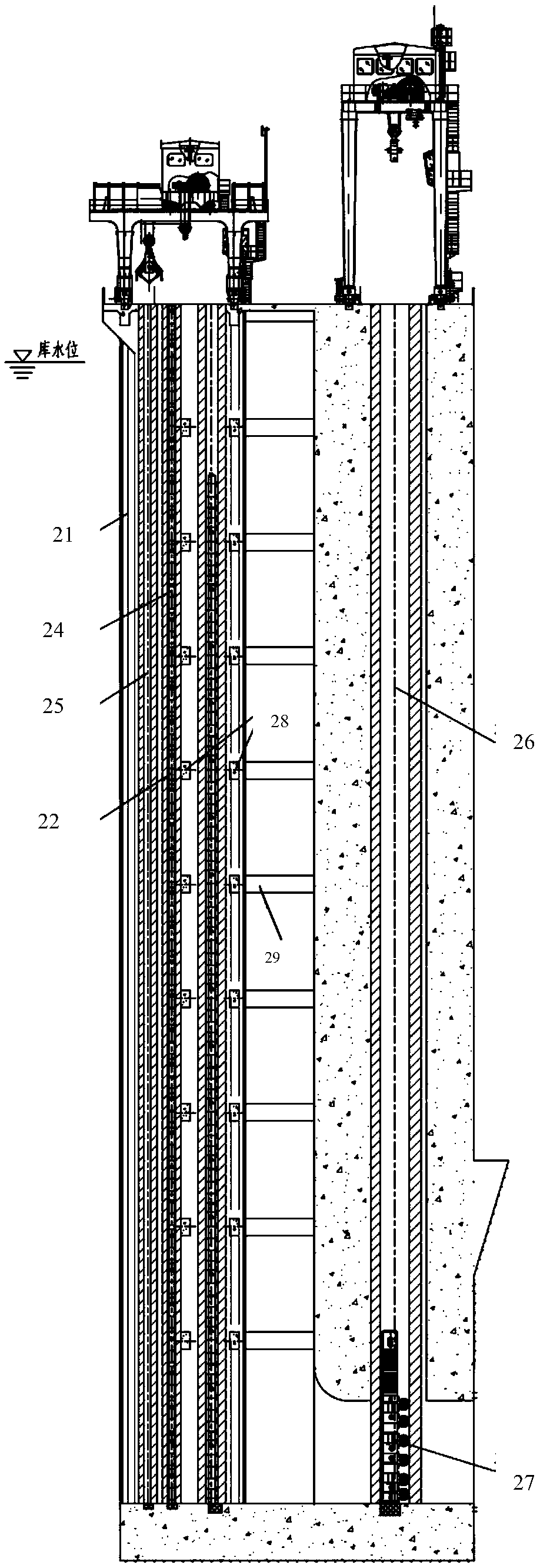
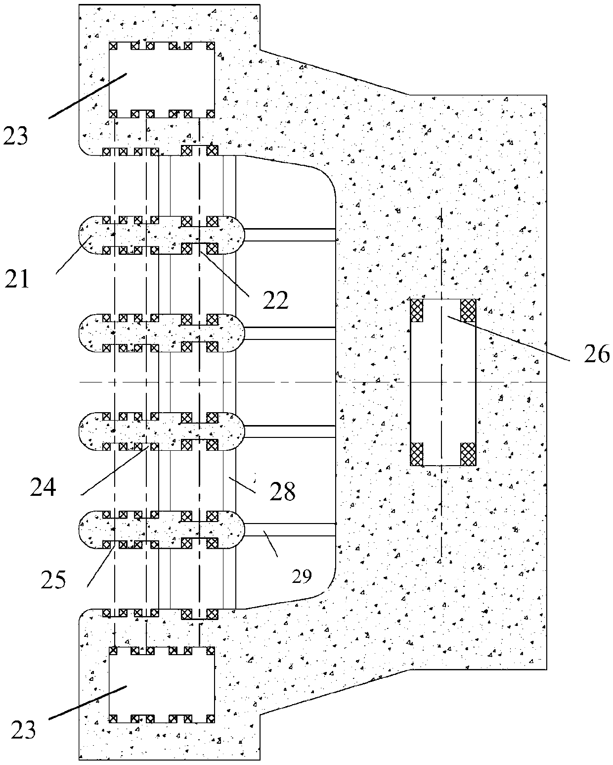
[0022] Such as Figure 5 , 6 As shown, the layered water intake independent water inlet tower structure used in high water head power stations of the present invention includes a bottom plate 1, a tower body 2, grid piers 3, trash racks 5, stacking beam door slots 6, and stacking beam door leaves 11 , stacked beam door storage 7, accident inspection door slot 8, ventilation hole 9, accident inspection maintenance gate 16, water diversion tunnel 14, trash rack 5 located in grid pier 3, stacked beam door slot 6, stacked beam door storage 7, accident inspection and repair The door slot 8 and the ventilation hole 9 are located in the tower body 2, and the multiple grid piers 3 located at the water inlet are connected by the beam 4 in turn to form a curved polygonal trash rack frame structure protruding toward the water inlet direction. Trash racks...


PUM

PropertyMeasurementUnit
Heightaaaaaaaaaa
Maximum widthaaaaaaaaaa

Abstract

The invention discloses a layered water-intake independent intake tower structure for a high water head power station. The structure comprises a bottom plate, a tower body, grille pillars, trash racks, a stoplog groove, stoplog blades, a stoplog reservoir, an accident inspection door slot, a vent hole, an accident inspection gate and a diversion tunnel, wherein the trash racks are positioned in the grille pillars; the stoplog groove, the stoplog reservoir, the accident inspection door slot and the vent hole are positioned in a tower body; the plurality of grille pillars, positioned at a waterinlet, are sequentially connected by means of cross beams, so that an arc-like polygonal trash rack frame structure which protrudes towards a water intake direction is formed; the trash racks are respectively arranged between the two adjacent grille pillars; the stoplog groove and the stoplog reservoir are arranged along the water flow direction; a fixed hydraulic headstock gear is installed on the tower top and on the top of the accident inspection door slot; the accident inspection gate is suspended under the fixed hydraulic headstock gear; the diversion tunnel is closed by using the fixed hydraulic headstock gear to descent the accident inspection gate along the accident inspection door slot. Due to the arrangement of the arc-like trash rack frame structure, the transverse water flow direction width at the front edge of the tower body is reduced, the area of the trash racks is enlarged, and the head loss is reduced.

Description

technical field [0001] The invention relates to a water inlet tower structure, in particular to a layered water intake independent water inlet tower structure for a high water head power station. Background technique [0002] For large and medium-sized hydropower projects with high dams and large reservoirs, the large storage capacity and depth of the reservoir cause the water temperature of the original natural river to change to a certain extent in terms of time and space distribution. The water temperature in the reservoir generally forms a vertical distribution, with high surface temperature and low bottom temperature. For the consideration of power generation efficiency, the water intake tower of the power station generally adopts deep hole water intake, so the temperature of the discharged water is lower than that of the original natural river, causing a certain degree of adverse impact on the downstream ecological environment. Therefore, it is necessary to take the su...

Claims


Application Information

Patent Timeline
IPC IPC(8): E02B9/04E02B5/08
CPCE02B5/085E02B9/04Y02E10/20
Inventor 武帅秦永涛李梅刘顺萍尉霄腾任堂金月宋慧陈刚吕勋博
Owner CHINA WATER RESOURCES BEIFANG INVESTIGATION DESIGN & RES
Features
  • R&D
  • Intellectual Property
  • Life Sciences
  • Materials
  • Tech Scout
  • Unparalleled Data Quality
  • Higher Quality Content
  • 60% Fewer Hallucinations
Learn More