A distributed photovoltaic power station monitoring device

A distributed photovoltaic and power station monitoring technology, which is applied in the direction of machines/supports, supporting machines, mechanical equipment, etc., can solve the problems that monitoring devices are not easy to install and fix, and cannot realize the rotation and height adjustment of multiple sets of detection heads and cameras. Achieve good detection and achieve the effect of fixed installation

Active Publication Date: 2020-06-05
SUZHOU EPOWER CORP LTD
View PDF8 Cites 0 Cited by
  • Summary
  • Abstract
  • Description
  • Claims
  • Application Information

AI Technical Summary

Problems solved by technology

[0002] Distributed photovoltaic power plants usually refer to power generation systems that use distributed resources, have a small installed capacity, and are arranged near users. It is generally connected to a power grid with a voltage level below 35 kV or lower. Photovoltaic modules, a distributed photovoltaic power station system that directly converts solar energy into electrical energy, the existing distributed photovoltaic power station monitoring device cannot meet people's needs, so a distributed photovoltaic power station monitoring device with more stable detection is needed; There are certain disadvantages in the use of photovoltaic power station monitoring devices. First, the distributed photovoltaic power station monitoring device cannot realize the rotation and height adjustment of multiple groups of detectors and cameras. Secondly, the monitoring device is not easy to install and fix. For this reason, we propose a A Distributed Photovoltaic Power Station Monitoring Device

Method used


Image

  • A distributed photovoltaic power station monitoring device
  • A distributed photovoltaic power station monitoring device
  • A distributed photovoltaic power station monitoring device

Examples


Embodiment Construction

[0025] In order to make the technical means, creative features, goals and effects achieved by the present invention easy to understand, the present invention will be further described below in conjunction with specific embodiments.

[0026] In the description of the present invention, it should be noted that the terms "upper", "lower", "inner", "outer", "front end", "rear end", "both ends", "one end", "another end" The orientation or positional relationship indicated by etc. is based on the orientation or positional relationship shown in the drawings, and is only for the convenience of describing the present invention and simplifying the description, rather than indicating or implying that the referred device or element must have a specific orientation, use a specific Azimuth configuration and operation, therefore, should not be construed as limiting the invention. In addition, the terms "first" and "second" are used for descriptive purposes only, and should not be understood ...


PUM


Abstract

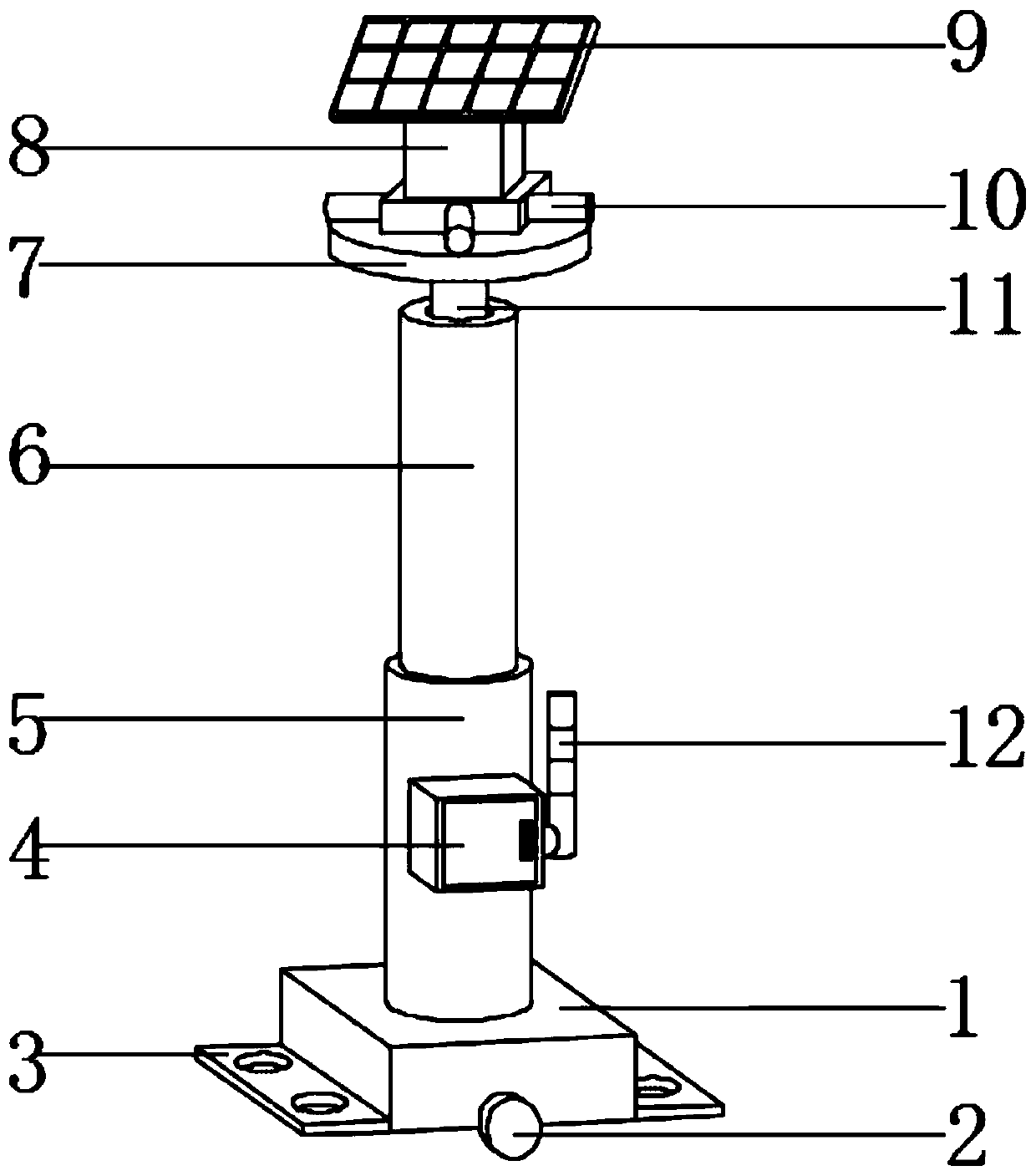
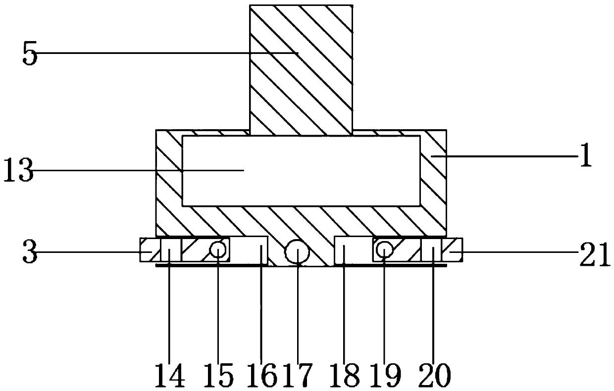
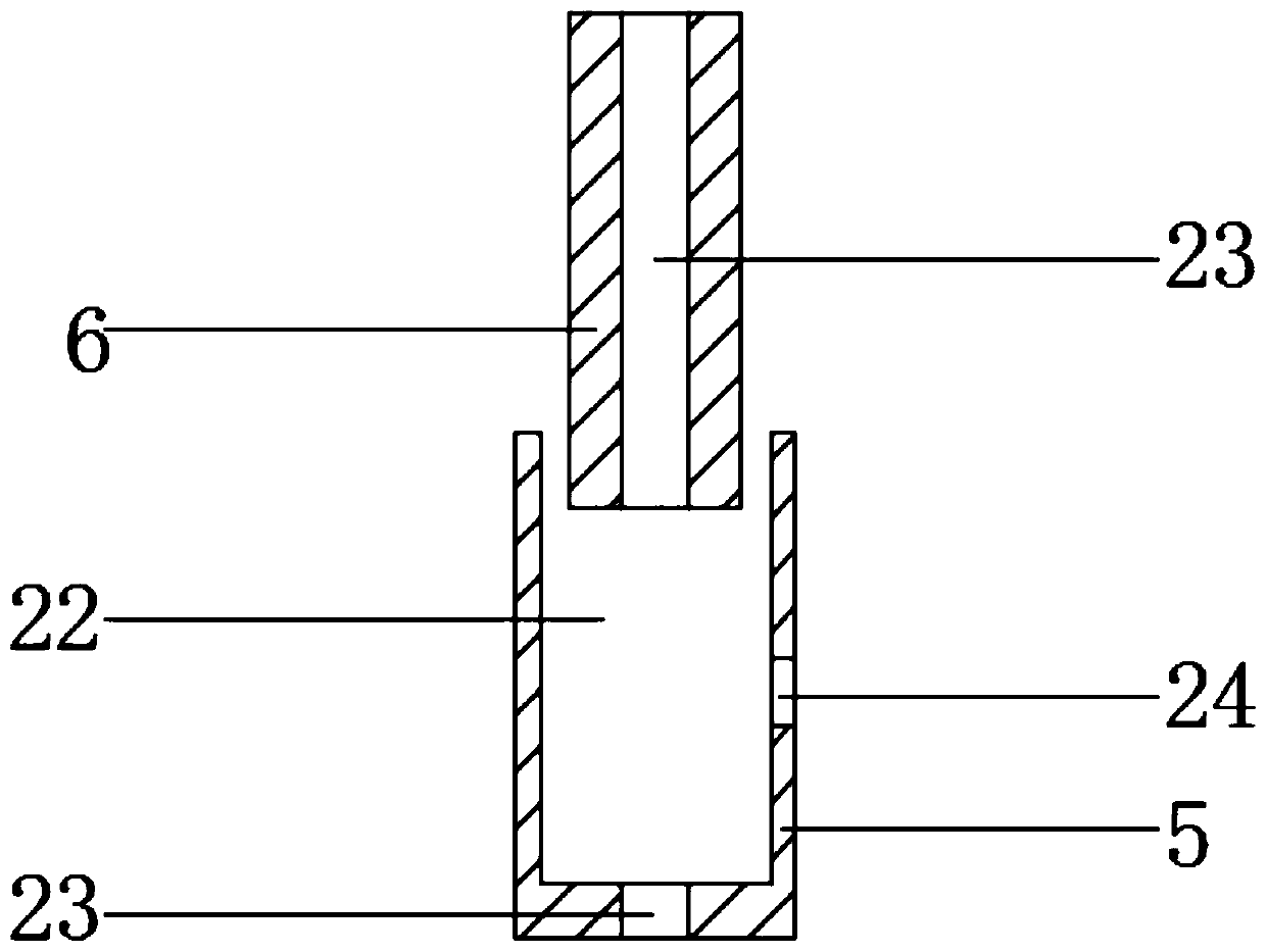
The invention discloses a distributive type photovoltaic power station monitoring device comprising a first base and a second base. Two wheels are installed on the middle portions of the front end andthe back end of the first base. The two wheels are connected with a wheel axle to be connected. A first installation groove is formed in the lower portion of one side of the first base. A first installation plate is arranged in the first installation groove. A first clamping rod is arranged at the position, close to the bottom of the first installation groove, of the first installation plate. Thetwo ends of the first clamping rod are inserted into the wall grooves of the first installation groove. A first installation hole is formed in the upper end of the first installation plate. The distributive type photovoltaic power station monitoring device is provided with a rotating structure, a telescopic structure, the installation plate and the second base, detectors and a camera can rotate,the height of the detectors can be conveniently adjusted, fixed installation of the monitoring device can be achieved, multiple groups of detectors can be arranged, and therefore the distributive typephotovoltaic power station monitoring device has certain practicability and brings better use prospect.

Description

technical field [0001] The invention relates to the field of auxiliary equipment for distributed photovoltaic power plants, in particular to a monitoring device for distributed photovoltaic power plants. Background technique [0002] Distributed photovoltaic power plants usually refer to power generation systems that use distributed resources, have a small installed capacity, and are arranged near users. It is generally connected to a power grid with a voltage level below 35 kV or lower. Photovoltaic modules, a distributed photovoltaic power station system that directly converts solar energy into electrical energy, the existing distributed photovoltaic power station monitoring device cannot meet people's needs, so a distributed photovoltaic power station monitoring device with more stable detection is needed; There are certain disadvantages in the use of photovoltaic power station monitoring devices. First, the distributed photovoltaic power station monitoring device cannot ...

Claims


Application Information

Patent Timeline
Patent Type & Authority Patents(China)
IPC IPC(8): F16M11/28F16M11/08F16M11/18
CPCF16M11/08F16M11/18F16M11/2014F16M11/28F16M2200/08
Inventor 袁楠张飞飞
Owner SUZHOU EPOWER CORP LTD
Why Eureka
Try Eureka