Wire coil distance deformation automatic detection device and detection method applying same

An automatic detection device and wire reel technology, applied in the direction of mechanical solid deformation measurement, mechanical gap measurement, etc., can solve the problems of uneven cylinder diameter, poor integrity, and excessive height difference of slats, etc., to achieve convenient and objective detection process , Reduce difficulty and risk, easy to use and flexible effects

Active Publication Date: 2019-04-23
铜陵精达新技术开发有限公司 +1
View PDF19 Cites 2 Cited by
  • Summary
  • Abstract
  • Description
  • Claims
  • Application Information

AI Technical Summary

Problems solved by technology

However, whether it is an all-wooden plate or a composite wooden plate, it is made by splicing, and its integrity is poor, and deformation, twisting, center deviation of the cylinder, uneven diameter of the cylinder, and excessively high height difference between the slats often occur. Problems, which affect the quality of the line body, and even lead to problems such as crimping during the unwinding process, so strict quality inspections must be carried out on the line reel from time to time
At present, the detection methods for all wooden discs and composite wooden discs mainly rely on tape measure, steel square and visual inspection. The operation is relatively cumbersome and time-consuming, and the test results are different due to the differences in the experience of the inspectors, so they cannot be effective. Ensure the quality of the reel to be used, which obviously increases the difficulty and risk of arranging and releasing the wires

Method used


Image

  • Wire coil distance deformation automatic detection device and detection method applying same
  • Wire coil distance deformation automatic detection device and detection method applying same
  • Wire coil distance deformation automatic detection device and detection method applying same

Examples


Embodiment Construction

[0038] For ease of understanding, combined here Figure 1-5, the concrete structure and working mode of the present invention are further described as follows:

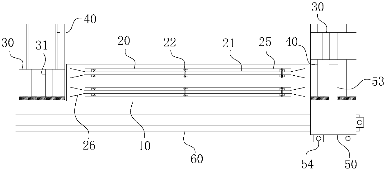
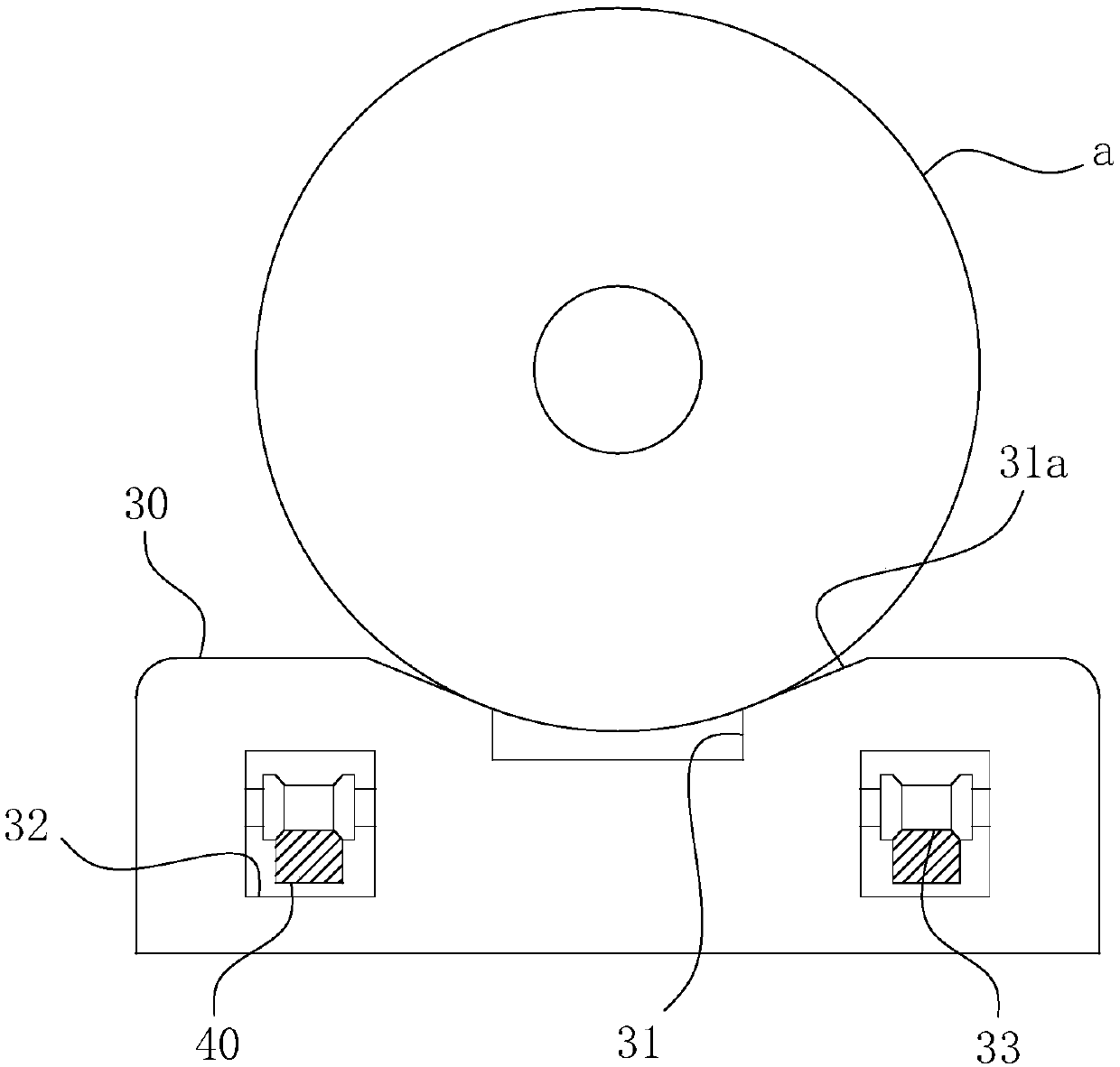
[0039] The specific structure of the present invention is as Figure 1-5 As shown, its main structure includes a base plate 10 with a detection belt 20, two sets of first guide rails 40, two sets of disk body positioning plates 30 located on each first guide rail 40, a set of second guide rails 60 and a set of second guide rails located on the second guide rails. A group of railcars 50 with positioning posts 53 on 60. in:

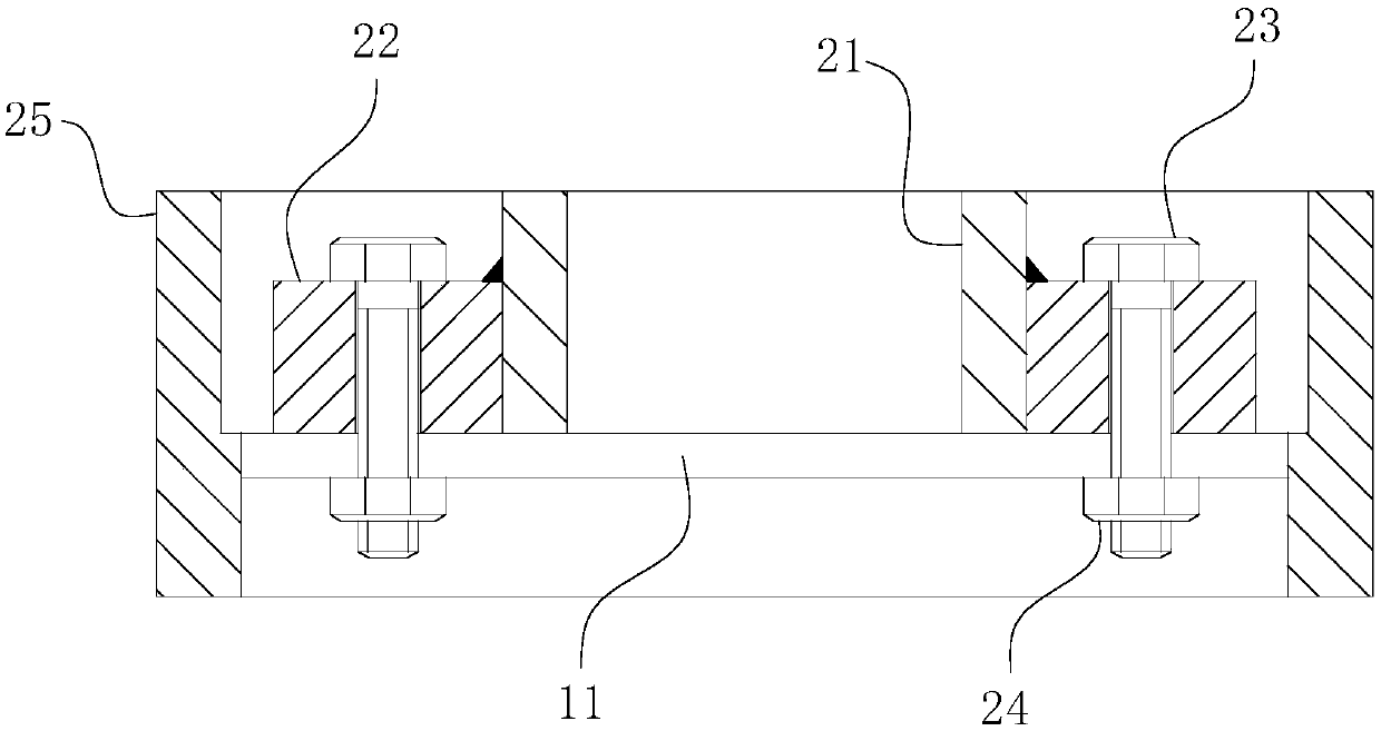
[0040] Detection band 20 is as the core component of the present invention, with Figure 1-2 Taking the structure as an example, the detection belt 20 includes four sets of detection plates 21 and four sets of limit plates 25 . along figure 1 In the direction shown, the detection zone 20 is subdivided into the first detection plate, the second detection plate, the third detection plate and the...


PUM


Abstract

The invention belongs to the technical field of wire coil distance deformation detection, and particularly relates to a wire coil distance deformation automatic detection device and a detection methodapplying the same. The wire coil distance deformation automatic detection device can conveniently and objectively detect wire coils and comprises a base plate; detection bands are arranged on the base plate, and each set of detection bands comprises two or more detection plates, wherein the plate faces of the detection plates are parallel to each other; and the lengths of the detection bands aregreater than or equal to the perimeters of the coil edges of the standby wire coils. The detection method comprises the steps: a positioning column of a rail car is inserted into coil holes of the standby wire coils; the rail car is started to advance along a second guide rail, the standby wire coils are driven by the rail car to rotate coaxially along the positioning column and meanwhile enter the detection bands, and at the moment, the corresponding coil edges of the standby wire coils are clamped into plate face gaps between the two sets of detection plates on the corresponding detection bands correspondingly; and then detection is started. According to the detection method, the detection efficiency and convenience can further be promoted.

Description

technical field [0001] The invention belongs to the technical field of detecting the deformation of wire and disc distance, and in particular relates to an automatic detection device and a detection method for the deformation of wire and disc distance. Background technique [0002] In the field of enameled wire production, the wire reels wound with copper wires or even finished enameled wires generally use full wooden reels or steel composite wooden reels. However, whether it is an all-wooden plate or a composite wooden plate, it is made by splicing, and its integrity is poor, and deformation, twisting, center deviation of the cylinder, uneven diameter of the cylinder, and excessively high height difference between the slats often occur. Problems, which affect the quality of the line body, and even lead to problems such as crimping during the unwinding process, so strict quality inspections must be carried out on the line reel from time to time. At present, the detection me...

Claims


Application Information

Patent Timeline
IPC IPC(8): G01B5/14G01B5/30
CPCG01B5/14G01B5/30
Inventor 陈鼎彪陈彬陈城曹永成黄亮汪洋孙玉好胡伯顺吴晓山张槐林吴智云黄爱军李齐靖秦磊王帮助查敏王建华
Owner 铜陵精达新技术开发有限公司
Why Eureka
Try Eureka