AI technical title is built by Patsnap AI team. It summarizes the technical point description of the patent document.
A technology for making prototypes and soil columns, applied in the field of geotechnical testing, can solve problems such as hindering in-depth research and engineering application of soil column physical mechanics, restricting stable acquisition of soil column related parameters, and increasing operating procedures, so as to achieve uniform force and smoothness. The effect of consistency and improved accuracy
Active Publication Date: 2021-07-23
CENT SOUTH UNIV
View PDF11 Cites 0 Cited by
Summary
Abstract
Description
Claims
Application Information
AI Technical Summary
This helps you quickly interpret patents by identifying the three key elements:
Problems solved by technology
Method used
Benefits of technology
Problems solved by technology
The compression method is one of the most commonly used methods for disturbing soil samples. The operation is relatively simple and the soil will not be disturbed by impact loads. However, it is difficult to maintain the same height, flatness and dry density of the samples when using the compression method. , holes may be formed in the soil body, and the static pressure demoulding is generally provided by the jack, which increases the operation process, and only one sample can be produced at a time, and the efficiency is low, which is difficult to meet the demand for large circular pie-shaped soil columns in college teaching experiments , also restricts the stable acquisition of relevant parameters of the soil column, and hinders the in-depth research and engineering application of soil column physical and mechanical parameters, so it is necessary to develop soil column sample preparation equipment
Method used
Image
Click on the blue label to locate the original text in one second.
Reading with bidirectional positioning of images and text.
Examples
Embodiment Construction
[0027] The specific implementation manners of the embodiments of the present invention will be described in detail below in conjunction with the accompanying drawings. It should be understood that the specific implementation manners described here are only used to illustrate and explain the embodiments of the present invention, and are not intended to limit the embodiments of the present invention.
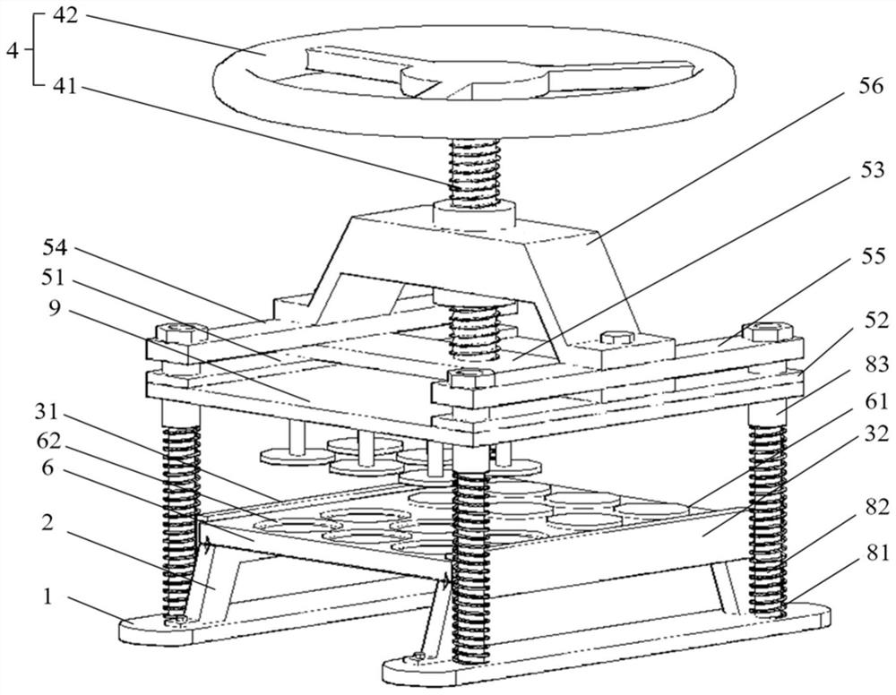
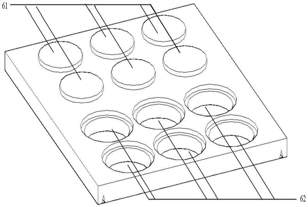
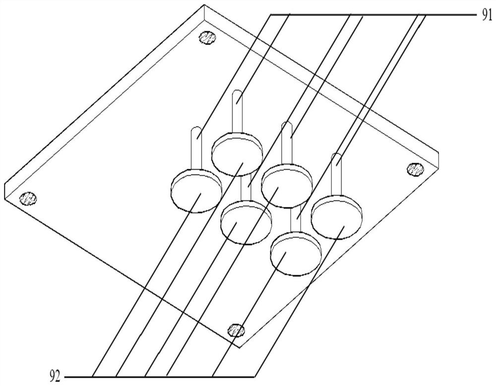
[0028] see Figure 1-Figure 9, the present invention provides a technical solution: a soil column sample making machine, including a base 1, a base frame 2, a limit assembly 3, a drive assembly 4, a support bracket 5, a stamping plate 9, a mold plate 6, a spring 81, and a sample preparation cylinder 71 and spacer 72, the upper end of the base 1 is welded with the base platform 2, the upper end of the support bracket 5 supports the driving assembly 4, the driving assembly 4 drives the stamping plate 9 to slide vertically, and the mold plate 6 slides horizontally between the base pl...
PUM
Property
Measurement
Unit
diameter
aaaaa
aaaaa
diameter
aaaaa
aaaaa
depth
aaaaa
aaaaa
Abstract
The invention belongs to the field of geotechnical testing, and discloses a soil column sample making machine, which includes a base, a base stand, a limit assembly, a drive assembly, a support bracket, a stamping plate, a mold plate, a spring, a sample preparation cylinder, and a cushion block. The upper end of the base is welded with a base stand, and the upper end of the support bracket supports the drive assembly, which drives the stamping plate to slide vertically, the die plate slides horizontally between the base stands, and the sample preparation cylinder is placed on the mold On the plate, the pad is placed on the upper side of the sample preparation cylinder, the limit assembly is fixed on the base frame, and the lower end of the spring is in contact with the base. The structure is simple, the operation is convenient, accurate and efficient, and the sample preparation process The soil column is evenly stressed, and the height, flatness and dry density of the produced soil column are basically the same. A lot of manpower.
Description
technical field [0001] The invention relates to a soil column sample making machine, which belongs to the technical field of geotechnical testing. Background technique [0002] Consolidation tests, direct shear tests, and density tests are all commonly used soil tests. The consolidation parameters of the soil sample under pressure can be obtained through the consolidation test, which can be used to evaluate the settlement amount and settlement time of the soil layer under the upper load. The shear strength parameters of the soil sample can be obtained through the direct shear test. To evaluate the strength of the soil and carry out stability calculation and analysis, the natural density of the undisturbed soil can be determined through the density test. Whether it is a consolidation test, a direct shear test or a density test, soil columns of the same size ( 6.18cm in diameter and 2.0cm in height) is the test object, and for college soil engineering tests, it is necessary t...
Claims
Application Information
Patent Timeline
Application Date:The date an application was filed.
Publication Date:The date a patent or application was officially published.
First Publication Date:The earliest publication date of a patent with the same application number.
Issue Date:Publication date of the patent grant document.
PCT Entry Date:The Entry date of PCT National Phase.
Estimated Expiry Date:The statutory expiry date of a patent right according to the Patent Law, and it is the longest term of protection that the patent right can achieve without the termination of the patent right due to other reasons(Term extension factor has been taken into account ).
Invalid Date:Actual expiry date is based on effective date or publication date of legal transaction data of invalid patent.

