A quick detachable busway

A bus duct and fast technology, applied in the field of bus duct, can solve the problems of inconvenient disassembly, complicated fixing method of the flame retardant partition and the side plate of the bus duct, low use efficiency, etc. The effect of replacement efficiency

Active Publication Date: 2020-05-08
CHONGQING JINGLI ELECTRICAL APPLIANCE CO LTD
View PDF4 Cites 0 Cited by
  • Summary
  • Abstract
  • Description
  • Claims
  • Application Information

AI Technical Summary

Problems solved by technology

[0004] The technical problem to be solved by the present invention is that the fixing method of the existing flame-retardant partition in the busway and the side plate of the busway is complicated. When maintenance is required, it is not easy to disassemble and the use efficiency is low. busway, to solve the connection problem between the flame retardant partition and the side plate of the busway

Method used


Image

  • A quick detachable busway
  • A quick detachable busway
  • A quick detachable busway

Examples


Embodiment 1

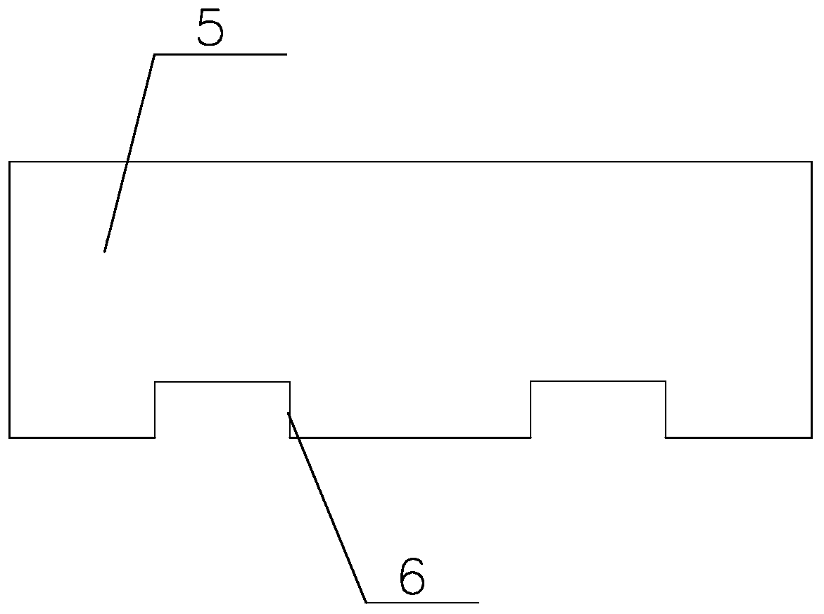
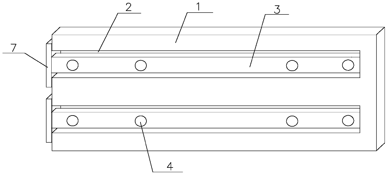
[0026] Such as Figure 1~2 As shown, a quick-detachable bus duct of the present invention includes a bus duct side plate 1 and a flame-retardant partition 5. Two first grooves 2 parallel to each other are arranged on the bus duct side plate 1. The first groove One end of 2 is in the side plate 1 of the bus duct, and the other end runs through one end of the side plate 1 of the bus duct. A connecting plate 3 is arranged in the first groove 2, and one end of the connecting plate 3 is connected with the spring, and the other end of the spring is connected with the first The groove 2 is connected to one end of the side plate 1 of the bus duct, and the other end of the connecting plate 3 is outside the first groove 2. Under the action of the spring, the connecting plate 3 moves along the straight line where the first groove 2 is located; the connecting plate 3 A through hole 4 for connecting the flame-retardant partition 5 is provided on the top, and the connecting plate 3 is drive...

Embodiment 2

[0028] A quick-detachable busway. On the basis of Embodiment 1, the connecting plate 3 is vertically connected with a positioning plate 7 on one end outside the side plate 1 of the busway. The positioning plate 7 is outside the side plate 1 of the busway. The positioning plate 7 An iron-absorbing layer is provided on the surface in contact with the side plate 1 of the bus duct, and the positioning plate 7 is fixedly connected with the side plate 1 of the bus duct through the iron-absorbing layer. The length of the connecting plate 3 is the same as that of the first groove 2 .

Embodiment 3

[0030] A quick-detachable bus duct, in the case of Embodiment 2, the diameter of the second groove 6 is the same as the diameter of the through hole 4 , and the depth of the second groove 6 is the same as the length of the through hole 4 . The height of the connecting plate 3 is two-thirds of the height of the first groove 2 .


PUM


Abstract

The invention discloses a bus groove capable of being fast dismounted.Through holes used for connecting a flame-retardant separation plate is arranged on each connecting plate; the connecting plates are driven to move through moving one ends, located outside a first groove, of the moving plates; under the effect of a spring, the first connecting plates are located outside the first groove; the through holes in the connecting plates are moved to a position outside the side plate of the bus groove; one end, connected with the bus groove side plate, of the flame-retardant separation plate is provided with a second groove corresponding to corresponding through holes in the two connecting plates; screw threads are formed in the second groove and the through holes; after the connecting plates are pulled out, screw rods with screw threads penetrate through the through holes to be fixedly connected with the second groove; after the connection, the connecting plates slide into the first groove,so that the flame-retardant separation plate is fixed onto the bus groove side plate. The invention has the advantages that under the condition of effectively improving the repair and replacement efficiency, the intensity of the bus groove per se cannot be influenced; the use is more convenient; the long-time use is convenient.

Description

technical field [0001] The invention relates to the field of bus ducts, in particular to a quickly detachable bus duct. Background technique [0002] The busway is a closed metal device composed of copper and aluminum busbar columns, which is used to distribute large power to various components of the decentralized system. In indoor low-voltage power transmission main line projects, wires and cables have been increasingly replaced. The closed bus duct (referred to as bus duct) is made of metal plates (steel plates or aluminum plates) as protective shells, conductive bars, insulating materials and The busbar system composed of related accessories. It can be made into a plug-in closed busbar with a plug-in junction box at intervals, or a feed-type closed busbar without a junction box in the middle. In the power supply system of high-rise buildings, the power and lighting lines are often set separately, and are composed of expansion bus duct, terminal head, terminal junction ...

Claims


Application Information

Patent Timeline
Patent Type & Authority Patents(China)
IPC IPC(8): H02G5/06
CPCH02G5/06
Inventor 彭翔田力廖光明
Owner CHONGQING JINGLI ELECTRICAL APPLIANCE CO LTD
Why Eureka
Try Eureka