Prefabricated laminated slab forming formwork

A technology for forming molds and laminated plates, applied in the direction of molds, etc., can solve the problems of increasing separation area, which is not conducive to the separation operation of prefabricated laminated plates and side molds, etc., and achieves the effect of improving the molding effect and the casting molding effect.

Active Publication Date: 2019-04-26
江苏若琪建筑产业有限公司
View PDF6 Cites 6 Cited by
  • Summary
  • Abstract
  • Description
  • Claims
  • Application Information

AI Technical Summary

Problems solved by technology

Due to the large contact area between the prefabricated laminated board and the side formwork, the required separation area increases when the side formwork is directly disassembled, which is not conducive to the separation of the prefabricated laminated board and the side formwork

Method used


Image

  • Prefabricated laminated slab forming formwork
  • Prefabricated laminated slab forming formwork
  • Prefabricated laminated slab forming formwork

Examples


Embodiment Construction

[0034] The present invention will be described in detail below in conjunction with the accompanying drawings and embodiments.

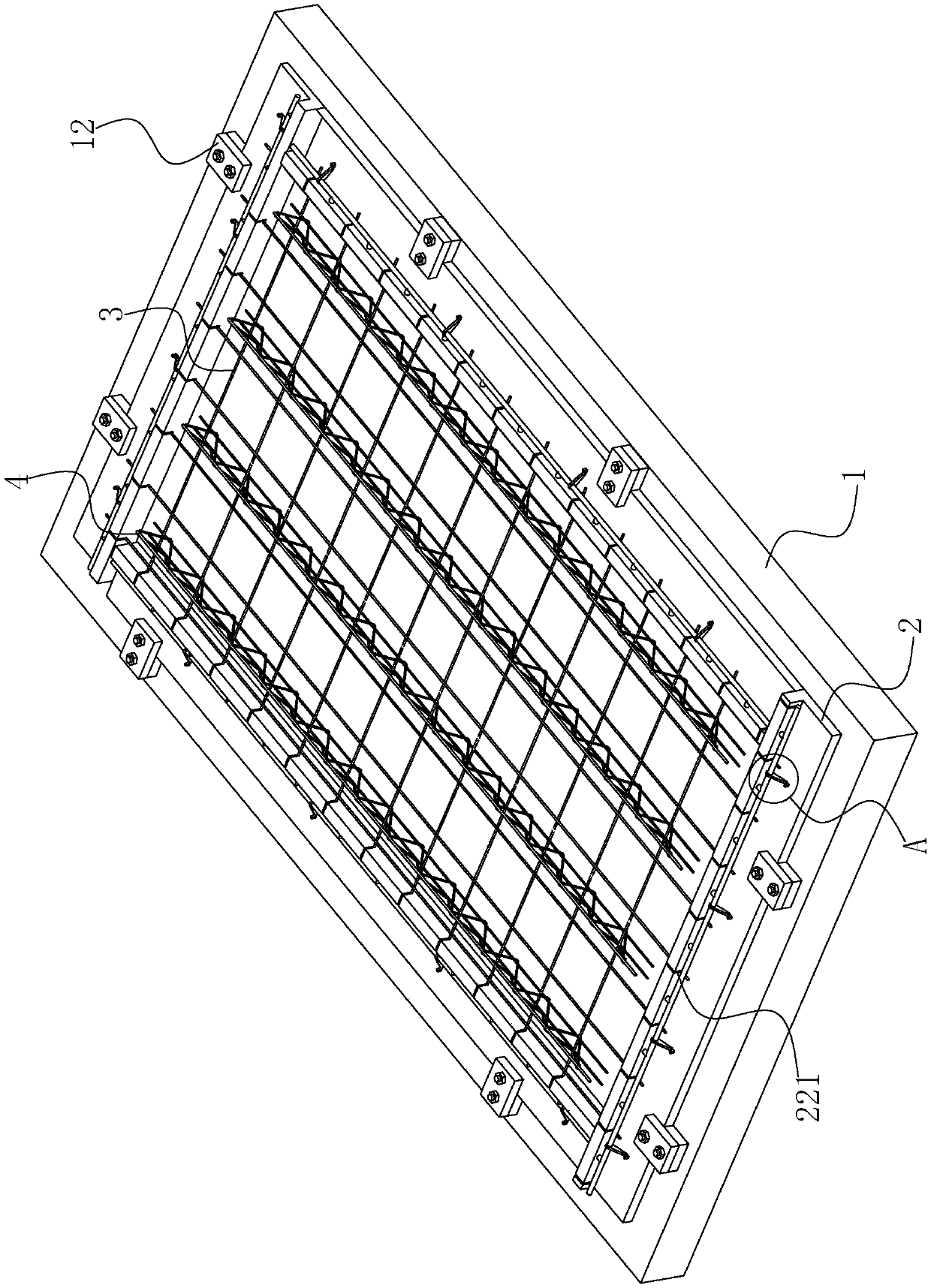
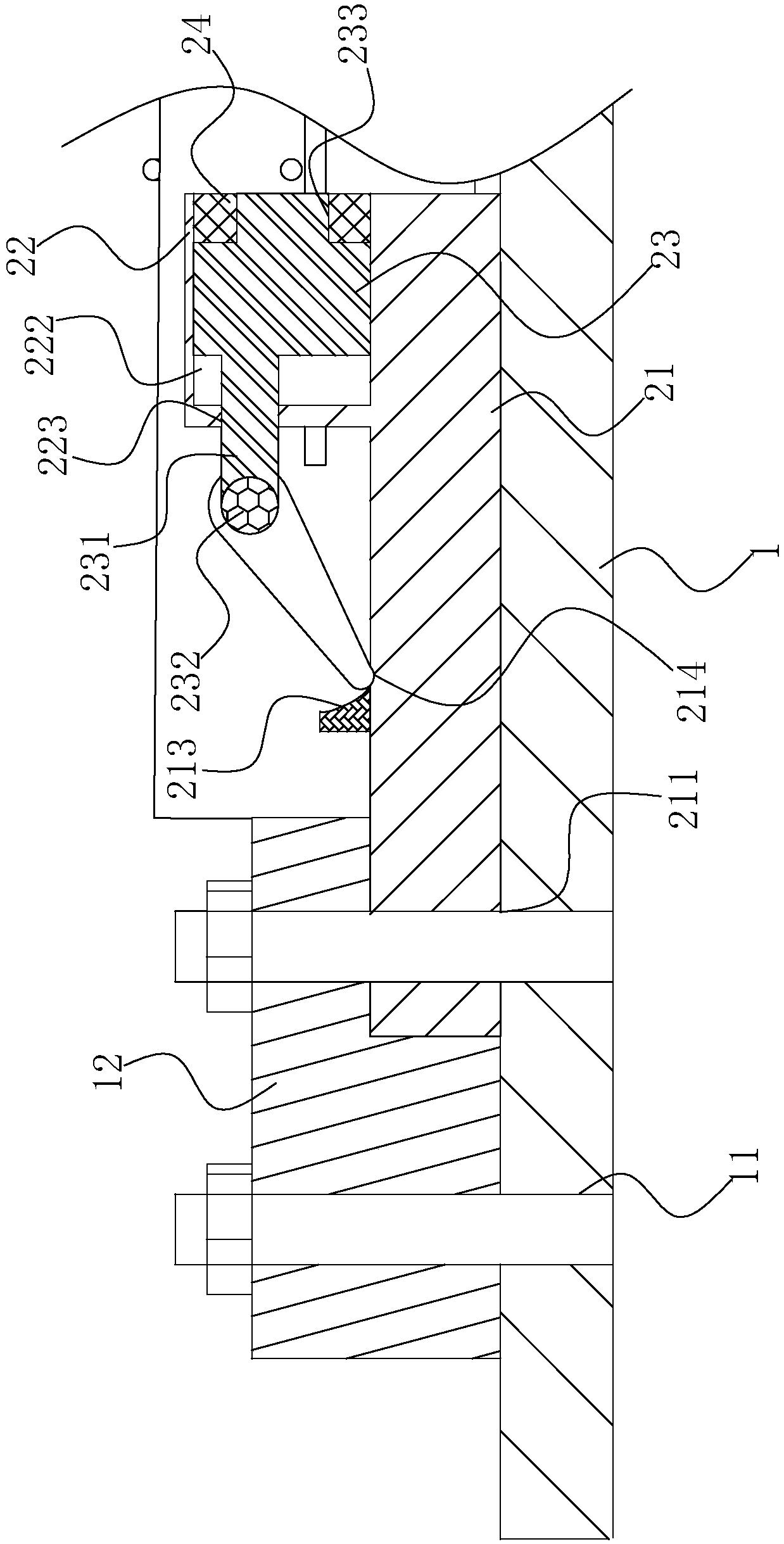
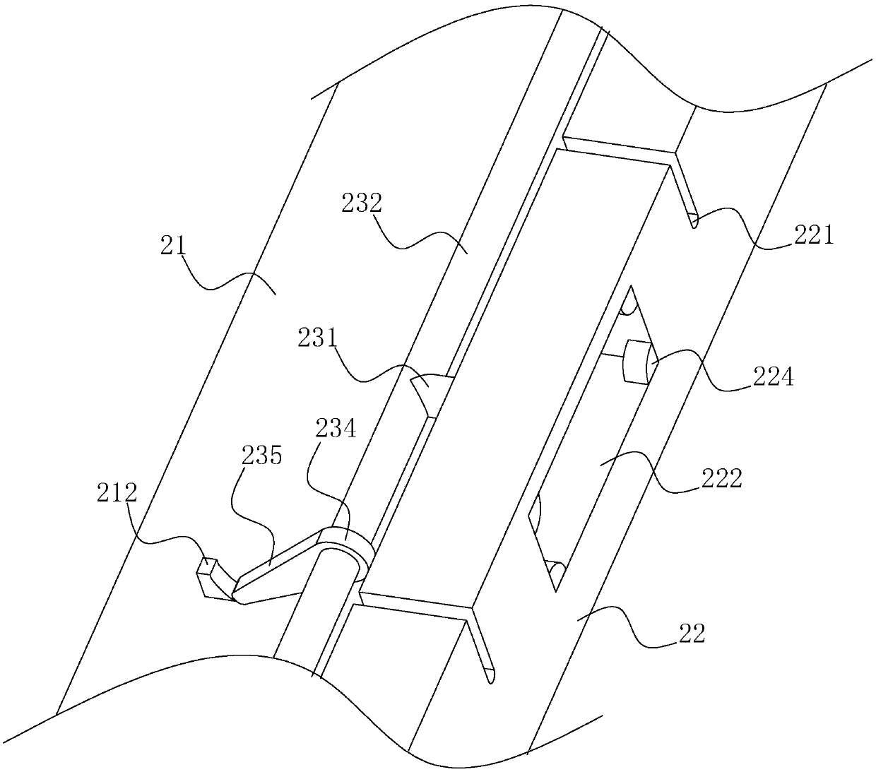
[0035] Embodiment, a kind of prefabricated laminated board forming mold, such as figure 1 , 2 As shown, it includes a mold table 1, a number of side molds 2 enclosed in a closed frame shape and installed and fixed on the mold table 1, and steel mesh 3 and truss steel bars placed on the mold table 1 within the enclosure of the side mold 2 4. The side formwork 2 is reserved with a relief slot 221 for the end of the reinforcement mesh 3 to pass through. The side mold 2 includes a bottom mold 21 and a side mold 22 integrally formed in an L shape. The bottom mold 21 is horizontally fixed on the mold table 1. The side mold 22 is located on the side of the bottom mold 21 adjacent to the reinforcement mesh 3. The side mold 22 faces the reinforcement mesh 3. One side is horizontally provided with sliding grooves 222, and several sliding grooves 222 are arran...


PUM


Abstract

The invention discloses a prefabricated laminated slab forming formwork and relates to the technical field of house prefabricated part production. By means of the prefabricated laminated slab formingformwork, the technical problems that the contact area of a prefabricated laminated slab and a side formwork is large, and separation operation of the prefabricated laminated slab and the side formwork cannot be conducted conveniently is solved. According to the technical scheme, the prefabricated laminated slab forming formwork comprises a formwork table, the side formwork, a rebar mesh and trussrebars, wherein the side formwork is enclosed and is in a closed frame state, and the rebar mesh is put inside the side formwork; a recession groove is reserved in the side formwork, wherein the recession groove allows the tail end of the rebar mesh to penetrate through; the side formwork comprises a bottom form and a side form, wherein the bottom form and the side form are integrally formed in an L shape; the face, facing the rebar mesh, of the side form is horizontally provided with sliding grooves; the multiple sliding grooves are formed in the length direction of the side form in an equally-spaced manner; attachment blocks are arranged in the sliding grooves in a sliding manner; sliding holes are horizontally formed in the groove bottoms of the sliding grooves in a penetrating manner;a push-pull rod is fixed to the face, facing the groove bottom of the corresponding sliding groove, of each attachment block, wherein the push-pull rods penetrate the sliding holes and horizontally extend out of the side form; and a linkage rod is connected between every two adjacent push-pull rods. The prefabricated laminated slab forming formwork has the advantages that the dismounting and separation actions of the side formwork and the prefabricated laminated slab can be carried out conveniently.

Description

technical field [0001] The invention relates to the technical field of building prefabricated components, more specifically, it relates to a prefabricated laminated plate molding die. Background technique [0002] The Chinese patent with the publication number CN108687939A discloses a general-purpose mold for building prefabricated component laminated panels, including four forming side mold assemblies, and the four forming side mold assemblies are formed by two-by-two vertical intersection and enclosing. An outer frame capable of forming and making a bottom mold of a prefabricated laminated plate, each of the forming side mold assemblies is provided with a bottom mold and a side mold, the cross-sectional width of the bottom mold is greater than that of the side mold, and the The bottom mold is fixedly arranged on the mold table, the side molds are fixed on the bottom mold, overhead gaskets and sealing strips are arranged between the bottom mold and the side molds, and the c...

Claims


Application Information

Patent Timeline
Patent Type & Authority Applications(China)
IPC IPC(8): B28B7/02
CPCB28B7/02
Inventor 冯勇军丁宁蒋若琪
Owner 江苏若琪建筑产业有限公司
Why Eureka
Try Eureka