A reference load and target load cross calibration track design method

A design method and load technology, applied in design optimization/simulation, calculation, genetic rules, etc., can solve problems such as large calibration errors and calibration reference changes, and achieve optimal crossover frequency and optimal crossover interval time

Active Publication Date: 2019-04-26
SHANGHAI AEROSPACE CONTROL TECH INST
View PDF3 Cites 2 Cited by
  • Summary
  • Abstract
  • Description
  • Claims
  • Application Information

AI Technical Summary

Problems solved by technology

When the time delay of the observation of the same target on the ground by the two loads is large, it will cause a large change in the calibration reference, which in turn will cause a large calibration error

Method used


Image

  • A reference load and target load cross calibration track design method
  • A reference load and target load cross calibration track design method
  • A reference load and target load cross calibration track design method

Examples


Embodiment Construction

[0026] In order to describe the technical content, structural features, achieved goals and effects of the present invention in detail, the following will be described in detail in conjunction with examples and accompanying drawings.

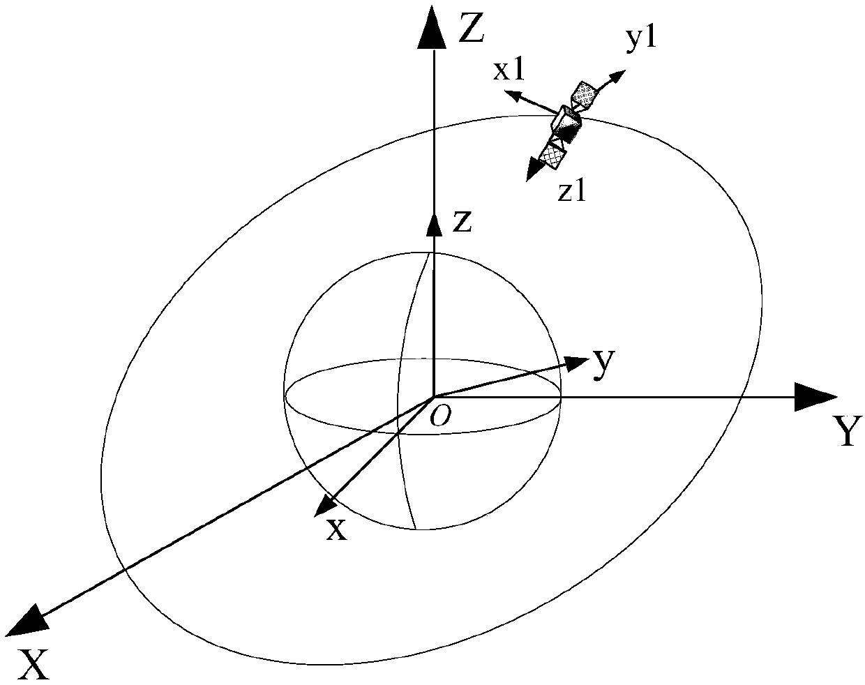
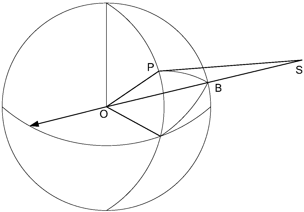
[0027] see Figure 1 to Figure 3 , a reference load and target load cross calibration track design method of the present invention comprises the following steps:

[0028] S1), establish the relative motion equation of the reference load and the target load on the ground calibration field, calculate the coverage time of the reference load and the target load on the ground calibration field respectively, and obtain two objective functions of crossing interval time and crossing frequency.

[0029] Coordinate transformation matrix C between the earth-centered inertial coordinate system and the earth-fixed system gi for

[0030] C gi =(EP)(ER)(NR)(PR)

[0031] In the formula, (PR) represents the precession matrix, (NR) represents the nutation matr...


PUM


Abstract

The invention discloses a reference load and target load cross calibration track design method. According to the method, an observation equation of a reference load and a target load for a specific ground calibration field is established according to task requirements of the reference load and the target load for cross calibration of the specific ground calibration field, and a fast non-dominatedsorting genetic algorithm NSGA-II is adopted for optimizing the reference load track, enabling the cross interval time of the reference load and the target load to meet the task requirement, and enabling the cross interval time to be the shortest and the cross frequency to be the maximum, so that the method is high in applicability, and the calibration efficiency of the reference load can be effectively improved.

Description

technical field [0001] The invention relates to a track design method, in particular to a reference load and target load cross calibration track design method. Background technique [0002] Due to the different orbits of the space reference payload satellite and the target payload satellite, the orbits of the sub-satellite points of each satellite are relatively different, and the opportunities for simultaneous observation of a specific calibration field on the ground are relatively small. When the time delay of the observation of the same target on the ground by the two loads is large, it will cause a large change in the calibration datum, which will lead to a large calibration error. [0003] In order to effectively improve the chance of simultaneous observation of a specific calibration field on the ground by the base load satellite and the target load satellite, and reduce the observation delay, it is necessary to carry out research on the joint observation cross-calibra...

Claims


Application Information

Patent Timeline
Patent Type & Authority Applications(China)
IPC IPC(8): G06F17/50G06F17/16G06N3/12G01C21/16G01C21/24
CPCG06F17/16G06N3/126G01C21/16G01C21/24G06F30/20Y02E60/00
Inventor 武海雷孙俊彭杨孙玥陈赟王有峰
Owner SHANGHAI AEROSPACE CONTROL TECH INST
Why Eureka
Try Eureka