
A kind of braiding method of cable braiding layer

A braiding layer and cable technology, which is applied in the direction of cable/conductor manufacturing, circuits, electrical components, etc., can solve problems such as low work efficiency, unstable wire laying, and manufacturing difficulties, and achieve the effect of realizing automation and reducing energy consumption

Active Publication Date: 2020-06-26
上海立鲲光电科技有限公司
View PDF9 Cites 0 Cited by
  • Summary
  • Abstract
  • Description
  • Claims
  • Application Information

AI Technical Summary

Problems solved by technology

[0002] Cable braiding machine refers to wrapping and braiding metal wire or fiber wire on the cable core or cable to achieve the purpose of protecting the cable core or cable. During the cable braiding process, it is necessary to pay attention to the uniformity of the wire or fiber wire wrapping and weaving. and density, but the actual production process is often accompanied by the phenomenon of thread breakage, which leads to work suspension and low work efficiency.
[0003] At present, the knitting machines on the market have complex structures and are difficult to manufacture. The pay-off is not stable, and the tension of the strands varies from time to time. When the wires are exhausted or broken, fast braking cannot be achieved, and weaving disorder occurs, which affects the quality of the product. and production efficiency

Method used


Image

  • A kind of braiding method of cable braiding layer
  • A kind of braiding method of cable braiding layer
  • A kind of braiding method of cable braiding layer

Examples


Embodiment 1

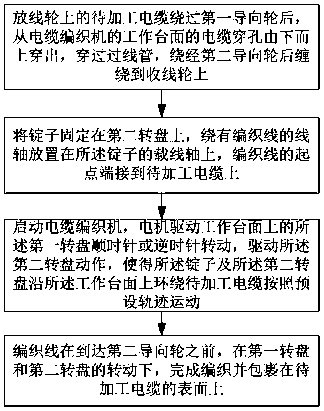
[0048] figure 1 It is a flowchart of a braiding method for a cable braiding layer of the present invention.

[0049] Such as figure 1 Shown, a kind of braiding method of cable braiding layer comprises:

[0050] After the cable to be processed on the pay-off wheel bypasses the first guide wheel, it passes through the cable hole on the working table of the cable braiding machine from bottom to top, passes through the wire tube, winds around the second guide wheel, and then winds up to the take-up wheel;

[0051] Fixing a plurality of spindles on the second turntable, placing a pay-off wheel wound with a braided wire on the wire-carrying shaft of the spindle, and the starting point of the braided wire is terminated on the cable to be processed;

[0052] Start the cable braiding machine, the motor drives the first turntable on the worktable to rotate, the driving force of the spindle is transmitted to the second turntable through the first turntable, that is, the first turntabl...

Embodiment 2

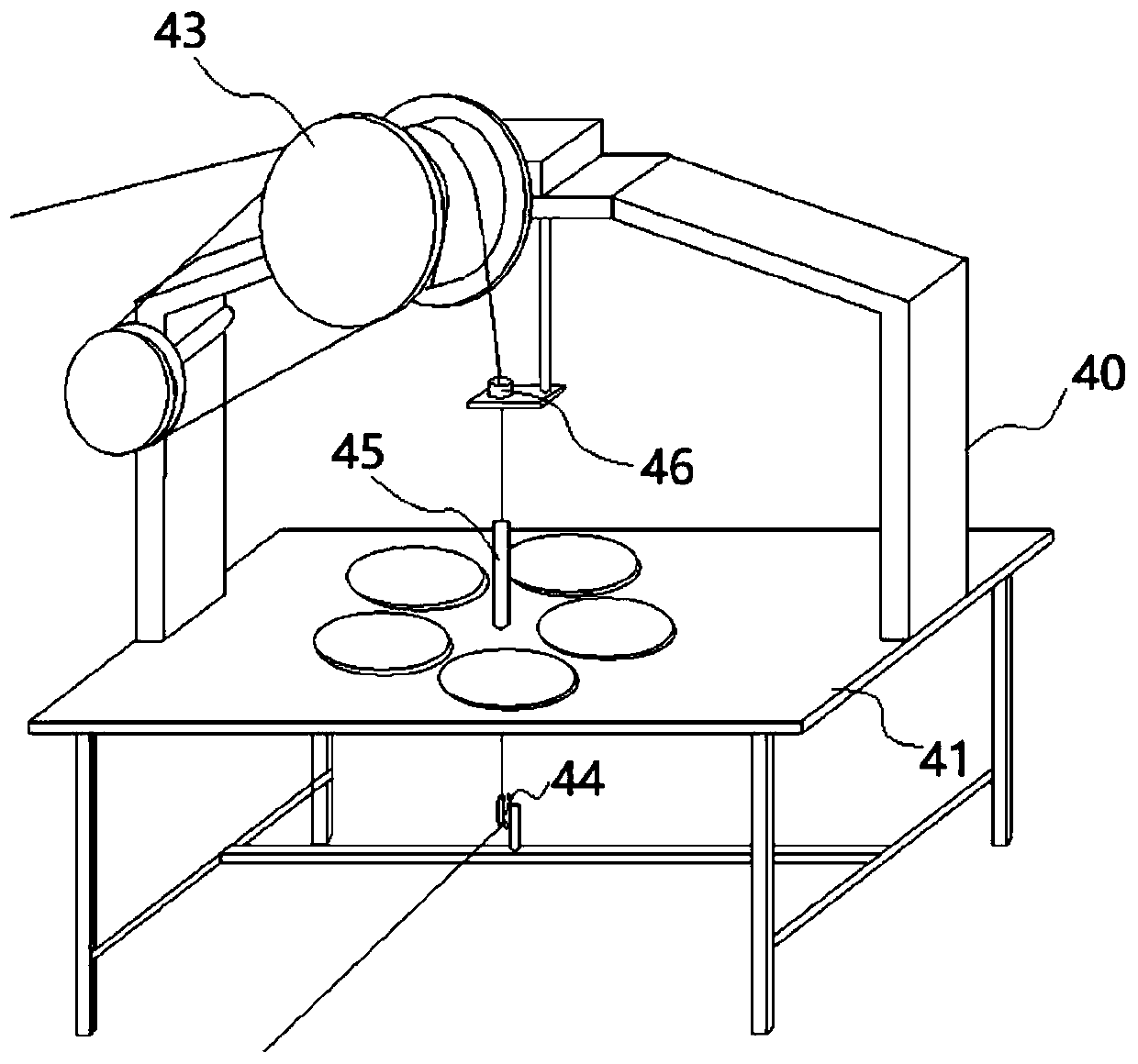
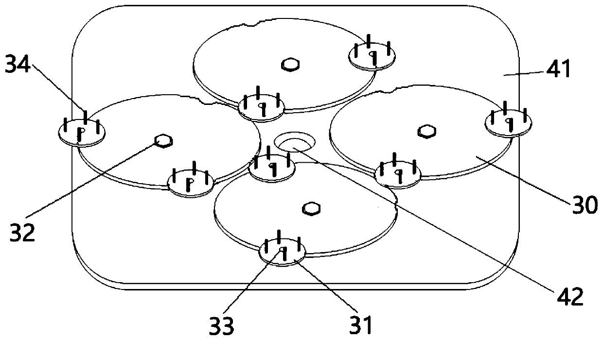
[0066] Such as Figure 2 ~ Figure 4 As shown, a cable braiding machine includes:

[0067] A frame 40, the frame 40 is provided with a working table 41; the working table 41 is provided with a plurality of braiding components. The braiding assembly is rotatably connected to the work surface 41 through the first rotating shaft 32 ; the center of the work surface 41 is provided with a cable through hole 42 . The cable through hole 42 is provided with a wire passing pipe 45 perpendicular to the work surface 41 , and the upper and lower ends of the wire passing pipe 45 respectively form a cable outlet hole and a cable inlet hole. The arrangement of the wire passing tube 45 ensures that the braided wires are naturally straightened before wrapping the outer shielding layer, and will not be deformed under the action of traction, reducing the probability of breakage.

[0068] At least one second guide wheel 43 is arranged above the working surface 41 , and the second guide wheel 43 i...

Embodiment 3

[0084] Such as Figure 5 As shown, the structure of this embodiment is basically the same as that of Embodiment 2, the difference is that:

[0085] There are two connecting shafts 5 of the spindle, which are arranged in parallel between the openings of the two side plates 2 . There is also a polished rod 17 between the two side plates 2, and the polished rod 17 is located below the pay-off wheel 21 and above the connecting shaft 5; the braided wire on the pay-off wheel 21 goes around one of the The third guide wheel 6 on the connecting shaft, the polished rod 17, the third guide wheel 6 on the other connecting shaft, and the fourth guide wheel 22 on the guide rod are output. Two connecting shafts are set, the up and down sliding of the slide block 7 can be made more stable, and it is more conducive to smooth unwinding.


PUM


Abstract

The invention provides a weaving method of a cable woven layer. The weaving method comprises the steps: a weaving line led out by a spindle is connected to the surface of a to-be-machined cable; the spindle is located on a second rotating disc, and the second rotating disc is located on a first rotating disc arranged around the to-be-machined cable; the first rotating disc rotates around the center axis of the first rotating disc, and thus the spindle and the second rotating disc are driven to move around the to-be-machined cable according to a preset track; in the process of forward moving ofthe to-be-machined cable, the weaving line is driven to move forwards and thus generates tension, an unwinding wheel of the spindle is driven through the tension to rotate, and thus the weaving lineis released from the unwinding wheel to be woven on the surface of the to-be-machined cable; and the woven cable is wound around a winding wheel. According to the weaving method provided by the invention, the tension of the weaving line can be adjusted at any moment, when the weaving line is used up or subjected to head breaking, braking is quickly achieved, and thus unwinding is stopped.

Description

technical field [0001] The invention relates to the field of wires and cables, in particular to a braiding method for a cable braiding layer. Background technique [0002] Cable braiding machine refers to wrapping and braiding metal wire or fiber wire on the cable core or cable to achieve the purpose of protecting the cable core or cable. During the cable braiding process, it is necessary to pay attention to the uniformity of the wire or fiber wire wrapping and weaving. And density, but the actual production process is often accompanied by the phenomenon of thread breakage, which leads to work suspension and low work efficiency. [0003] At present, the knitting machines on the market have complex structures and are difficult to manufacture. The pay-off is not stable, and the tension of the strands varies from time to time. When the wires are exhausted or broken, fast braking cannot be achieved, and weaving disorder occurs, which affects the quality of the product. and prod...

Claims


Application Information

Patent Timeline
Patent Type & Authority Patents(China)
IPC IPC(8): H01B13/26
CPCH01B13/2606
Inventor 宋志涛王柏然邓舜禹
Owner 上海立鲲光电科技有限公司
Learn More