Professional dual-power automatic transfer switching equipment

A technology of automatic transfer switch and dual power supply, which is applied in the direction of electric switches, circuits, electrical components, etc., can solve the problems of increasing the cost of professional dual-power automatic transfer switch electrical appliances, and achieve the ability to improve the rated short-circuit current limit, reduce costs, and structure Scientific and reasonable effect

Active Publication Date: 2019-04-26
沈阳斯沃电器有限公司
View PDF3 Cites 6 Cited by
  • Summary
  • Abstract
  • Description
  • Claims
  • Application Information

AI Technical Summary

Problems solved by technology

[0002] A low-voltage electrical appliance is a component or device that can manually or automatically switch on and off a circuit according to external signals and requirements to realize switching, control, protection, detection, transformation and adjustment of circuits or non-electrical objects. The dual power automatic transfer switch is a low-voltage electrical appliance. The structure of the dual power automatic transfer switch on the market is the upper and lower contacts. Because of the repulsive force between the contacts during the contact process, the rated limit is reduced due to the existence of the repulsive force. Short-circuit current, so the rated limit short-circuit current of the snap-fit ​​contact structure will not be very high, and in order to improve product parameters, the contacts have silver points, which increases the cost of professional dual-power automatic transfer switch appliances, so a professional type is urgently needed Double power supply automatic transfer switch electrical appliances to solve the above problems

Method used


Image

  • Professional dual-power automatic transfer switching equipment
  • Professional dual-power automatic transfer switching equipment
  • Professional dual-power automatic transfer switching equipment

Examples


Embodiment

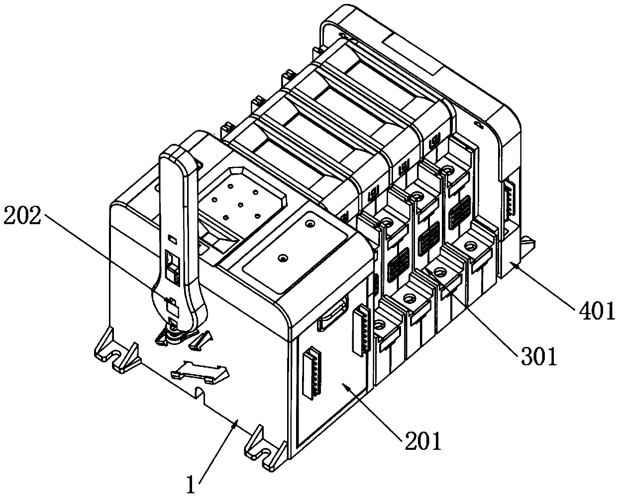
[0037] Example: such as Figure 1-9 As shown, the present invention provides a technical solution, a professional dual-power automatic transfer switch electrical appliance, including a mounting shell 1, and an operating component 2 is installed on one side of the mounting shell 1;

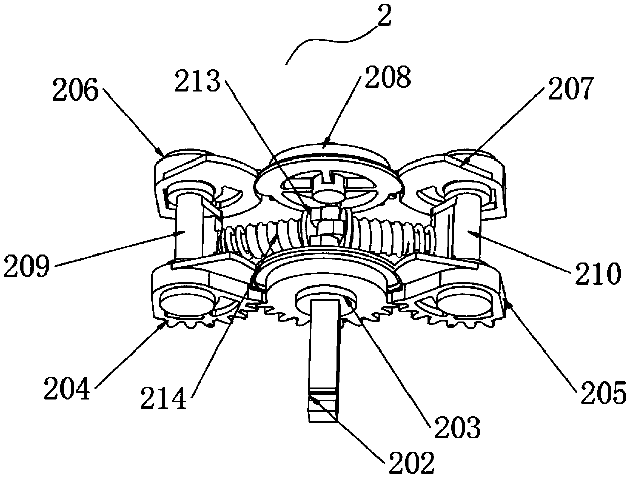
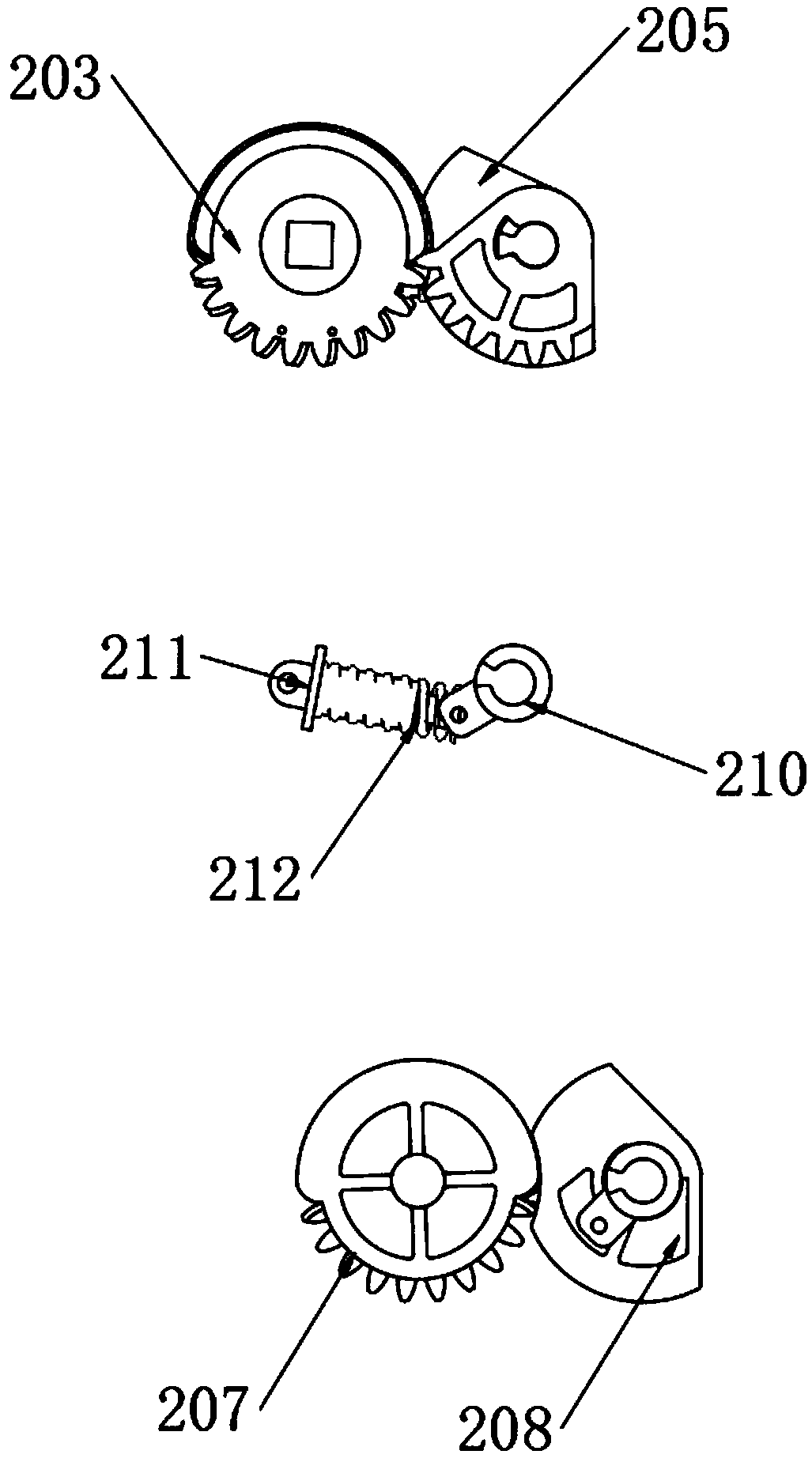
[0038] The operation assembly 2 includes an operation box 201, a connecting shaft 202, a driving wheel 203, a second main linkage gear 204, a first main linkage gear 205, a second slave linkage gear 206, a first slave linkage gear 207, a driven wheel 208, and a first crank 209 , the second crank 210, the first guide rod 211, the first connection spring 212, the second guide rod 213 and the second connection spring 214;

[0039]One side of the installation shell 1 is fixed with an operation box 201, and one side of the operation box 201 is embedded with a connecting shaft 202. One end of the connecting shaft 202 is connected with a driving wheel 203, and one side of the driving wheel 203 is meshed w...


PUM


Abstract

The invention discloses professional dual-power automatic transfer switching equipment. The professional dual-power automatic transfer switching equipment comprises a mounting shell, an operating component is mounted on one side of the mounting shell, monopole components are mounted on one side of the operating component, and an auxiliary contact component is mounted on one side the monopole components. The professional dual-power automatic transfer switching equipment is scientific and reasonable in structure and safe and convenient to use, through the linkage function of the operating component, the monopole components and the auxiliary contact component, completion of switching on a first power source and a second power source is facilitated, the opening and closing speed of contacts isincreased, the rated limited short-circuit current capability is improved, and parameters of the professional dual-power automatic transfer switching equipment are improved; the contacts have no silver point structure, so that the cost of the professional dual-power automatic transfer switching equipment is reduced, and the design of the professional dual-power automatic transfer switching equipment with low cost and high parameters is realized; and the position situation of the internal contacts can be conveniently and clearly seen through the function of inspecting windows, and the use is safer.

Description

technical field [0001] The invention relates to the technical field of low-voltage electrical appliances, in particular to a professional dual-power automatic switch electrical appliance. Background technique [0002] Low-voltage electrical appliances are components or devices that can manually or automatically switch on and off circuits according to external signals and requirements, so as to realize switching, control, protection, detection, transformation and adjustment of circuits or non-electrical objects. The dual power automatic transfer switch is a low-voltage electrical appliance. The structure of the dual power automatic transfer switch on the market is the upper and lower contacts. Because of the repulsive force between the contacts during the contact process, the rated limit is reduced due to the existence of the repulsive force. Short-circuit current, so the rated limit short-circuit current of the snap-fit ​​contact structure will not be very high, and in order...

Claims


Application Information

Patent Timeline
Patent Type & Authority Applications(China)
IPC IPC(8): H01H3/32H01H3/40H01H9/00H01H9/02H01H9/24H01H9/34
CPCH01H3/32H01H3/40H01H9/00H01H9/0066H01H9/02H01H9/24H01H9/34H01H2009/0292
Inventor 苏国臣解浩张平刘延苏
Owner 沈阳斯沃电器有限公司
Why Eureka
Try Eureka