
New microstrip line type band-pass filter

A band-pass filter and microstrip line technology, applied in waveguide-type devices, electrical components, circuits, etc., can solve problems such as difficult to meet, achieve compact structure, ensure coupling, and achieve the effect of miniaturized design requirements

Inactive Publication Date: 2019-04-26
GUIZHOU AEROSPACE ELECTRONICS TECH CO LTD
View PDF3 Cites 0 Cited by
  • Summary
  • Abstract
  • Description
  • Claims
  • Application Information

AI Technical Summary

Problems solved by technology

For example, when a half-wavelength parallel coupling filter with a center frequency of 2.75 GHz is designed using a 4th-order coupling line segment, and Rogers RT6010 is selected as the dielectric substrate material, the overall size of the filter is about 40mm×7mm, which is difficult to meet the needs of modern miniaturized products

Method used


Image

  • New microstrip line type band-pass filter
  • New microstrip line type band-pass filter
  • New microstrip line type band-pass filter

Examples


Embodiment Construction

[0018] The technical solution of the present invention is further described below, but the scope of protection is not limited to the description.

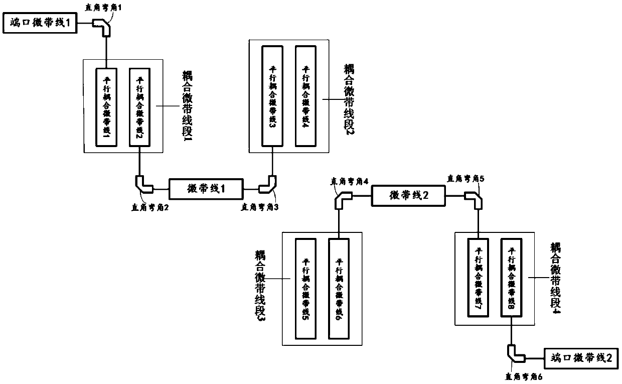
[0019] A novel microstrip line-type bandpass filter provided by the present invention includes a port microstrip line 1, a port microstrip line 2, a microstrip connection line 1, a microstrip connection line 2, a parallel coupling microstrip line segment 1, a parallel coupling Microstrip line segment 2, parallel coupled microstrip line segment 3, parallel coupled microstrip line segment 4, right angle bend 1, right angle bend 2, right angle bend 3, right angle bend 4, right angle bend 5, right angle bend 6, all The port microstrip line 1 is connected to the coupling microstrip line segment 1 through a right-angle bend 1, and the coupling microstrip line segment 1 and the coupling microstrip line segment 2 are connected through a right-angle bend 2, a microstrip connection line 1, and a right-angle bend 3 to form a U-shaped connectio...


PUM


Abstract

The invention provides a new microstrip line type band-pass filter which comprises a port microstrip line 1, a port microstrip line 2, a microstrip connection line 1, a microstrip connection line 2, aparallel coupling microstrip line segment 1, a parallel coupling microstrip line segment 2, a parallel coupling microstrip line segment 3, a parallel coupling microstrip line segment 4, a right-anglecorner 1, a right-angle corner 2, a right-angle corner 3, a right-angle corner 4, a right-angle corner 5 and a right-angle corner 6, wherein the port microstrip line 1 is connected with the couplingmicrostrip line segment 1 by the right-angle corner 1, the coupling microstrip line segment 1 is connected with the coupling microstrip line segment 2 by the right-angle corner 2, the microstrip connection line 1 and the right-angle corner 3 form U-shaped connection, the coupling microstrip line segment 3 and the coupling microstrip line segment 4 form inverted U-shaped connection through the right-angle corner 4, the microstrip connection line 2 and the right-angle corner 5, and the coupling microstrip line segment 4 is connected with the port microstrip line 2 by the right-angle corner 6. The outline structure of the traditional parallel coupling microstrip line band-pass filter is optimized, and the miniaturization design requirement is met.

Description

technical field [0001] The invention relates to a novel microstrip line-type band-pass filter. Background technique [0002] With the rapid development of short-distance wireless communication technology, band-pass filters in this frequency band have become a research hotspot. Microstrip bandpass filters are widely used in wireless communication systems due to their advantages of simple design, convenient fabrication, small size, low cost, high precision and easy integration. The half-wavelength parallel coupled bandpass filter consists of multiple parallel coupled line segments cascaded to each other to form a resonant circuit. It has the characteristics of small size, good out-of-band suppression and convenient design. It is the most commonly used filter in the microstrip bandpass filter. device. Parallel coupling filters have the properties of stepped impedance filters, each coupling line segment is approximately a quarter wavelength of the center frequency, and the wav...

Claims


Application Information

Patent Timeline
Patent Type & Authority Applications(China)
IPC IPC(8): H01P1/203
CPCH01P1/203
Inventor 刘文
Owner GUIZHOU AEROSPACE ELECTRONICS TECH CO LTD
Learn More