A radar liquid cooling device

A liquid cooling and radar technology, applied in the direction of cooling/ventilation/heating transformation, electrical components, electrical equipment structural parts, etc., can solve the problems of complex liquid cooling pipeline structure and hindering the miniaturization of liquid cooling devices

Active Publication Date: 2021-09-10
SICHUAN SIAIPU ELECTRONICS TECH CO LTD
View PDF7 Cites 0 Cited by
  • Summary
  • Abstract
  • Description
  • Claims
  • Application Information

AI Technical Summary

Problems solved by technology

In the existing technology, the liquid-cooled pipeline system often uses two or more pipes to transport the coolant, that is, the inlet and outlet channels of the liquid-cooled plate are located at two or more places on the liquid-cooled plate. This structure leads to a complex structure of the liquid cooling pipeline, hinders the further miniaturization of the liquid cooling device, and has certain reliability risks

Method used


Image

  • A radar liquid cooling device
  • A radar liquid cooling device
  • A radar liquid cooling device

Examples


Embodiment Construction

[0032] In order to make the purpose, technical solutions and advantages of the embodiments of the present invention clearer, the embodiments of the present invention will be described in detail below in conjunction with the accompanying drawings, but the embodiments described in the present invention are some of the embodiments of the present invention, not all of them .

[0033] It should be noted that like numerals and letters denote similar items in the following figures, therefore, once an item is defined in one figure, it does not require further definition and explanation in subsequent figures.

[0034] In describing the present invention, it should be noted that the terms "centre", "upper", "lower", "left", "right", "vertical", "horizontal", "inner", "outer" etc. indicate The orientation or positional relationship of the invention is based on the orientation or positional relationship shown in the drawings, or the orientation or positional relationship that is usually p...


PUM


Abstract

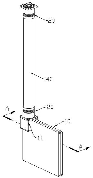
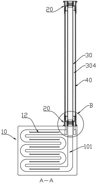
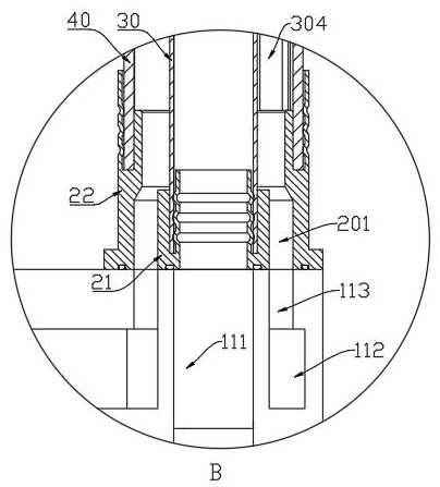
A radar liquid cooling device, comprising: a liquid cooling plate and a pipe joint. There is a flow channel inside the liquid cooling plate, and a connection port is provided on one side of the liquid cooling plate. The connecting port includes a connecting pipe. Located on the outside of the connecting pipe, one end of the flow channel is connected with the connecting pipe, and the other end is connected with the annular groove; the pipe joint is coaxially provided with an inner pipe and an outer pipe, and there is an annular cavity between the inner pipe and the outer pipe, and the bottom of the pipe joint is connected with the outer pipe. The connection port is connected, the inner pipe is connected with the connecting pipe, the outer pipe is in contact with the liquid cooling plate, and the annular cavity is connected with the annular hole; the upper end surface of the inner pipe is processed with an inner annular groove, and an inner pipe is embedded in the inner annular groove; the outer pipe An outer annular groove is processed on the upper end surface of the outer annular groove, and an outer pipe is embedded in the outer annular groove, and the annular gap communicates with the annular cavity and the annular hole. Reduce the position of flow channel joints, improve the reliability of the structure, simplify the liquid cooling pipeline, and further miniaturize the liquid cooling device.

Description

technical field [0001] The invention belongs to the technical field of radar environment control systems, and in particular relates to a radar liquid cooling device. Background technique [0002] With the development of technology, modern radar systems are developing in the direction of high power, integration, and miniaturization, and the cooling system of radars is increasingly cooled by miniaturized liquid cooling devices. The miniaturization of liquid cooling devices is affected by the miniaturization of system components such as liquid cooling plates, cooling pumps, heat exchange devices, and liquid cooling pipelines. In the existing technology, the liquid cooling pipeline system often uses double or multiple pipes to transport the cooling liquid, that is, the liquid inlet channel opening and the liquid outlet channel opening of the liquid cooling plate are respectively located at two or more places on the liquid cooling plate. Such a structure leads to a complex struc...

Claims


Application Information

Patent Timeline
Patent Type & Authority Patents(China)
IPC IPC(8): H05K7/20
CPCH05K7/20272
Inventor 罗亮
Owner SICHUAN SIAIPU ELECTRONICS TECH CO LTD
Why Eureka
Try Eureka