Direct current ice-melting short-circuit control structure

A DC ice-melting and short-circuiting technology, applied in the installation of electrical components, cables, overhead installation, etc., can solve the problems of many human resources, low work efficiency, and large ice-melting power, saving human resources and improving the use efficiency. , the effect of reducing the cost of melting ice time

Pending Publication Date: 2019-04-26
GUIZHOU POWER GRID CO LTD
View PDF0 Cites 2 Cited by
  • Summary
  • Abstract
  • Description
  • Claims
  • Application Information

AI Technical Summary

Problems solved by technology

However, this solution needs to install electric heating elements on the lines that may be covered with ice. The cost is high, the time is long, the human resources are large, the work efficiency is low, the risk of personnel is high during operation, and the power required for melting ice is also large.

Method used


Image

  • Direct current ice-melting short-circuit control structure
  • Direct current ice-melting short-circuit control structure
  • Direct current ice-melting short-circuit control structure

Examples


Embodiment 1

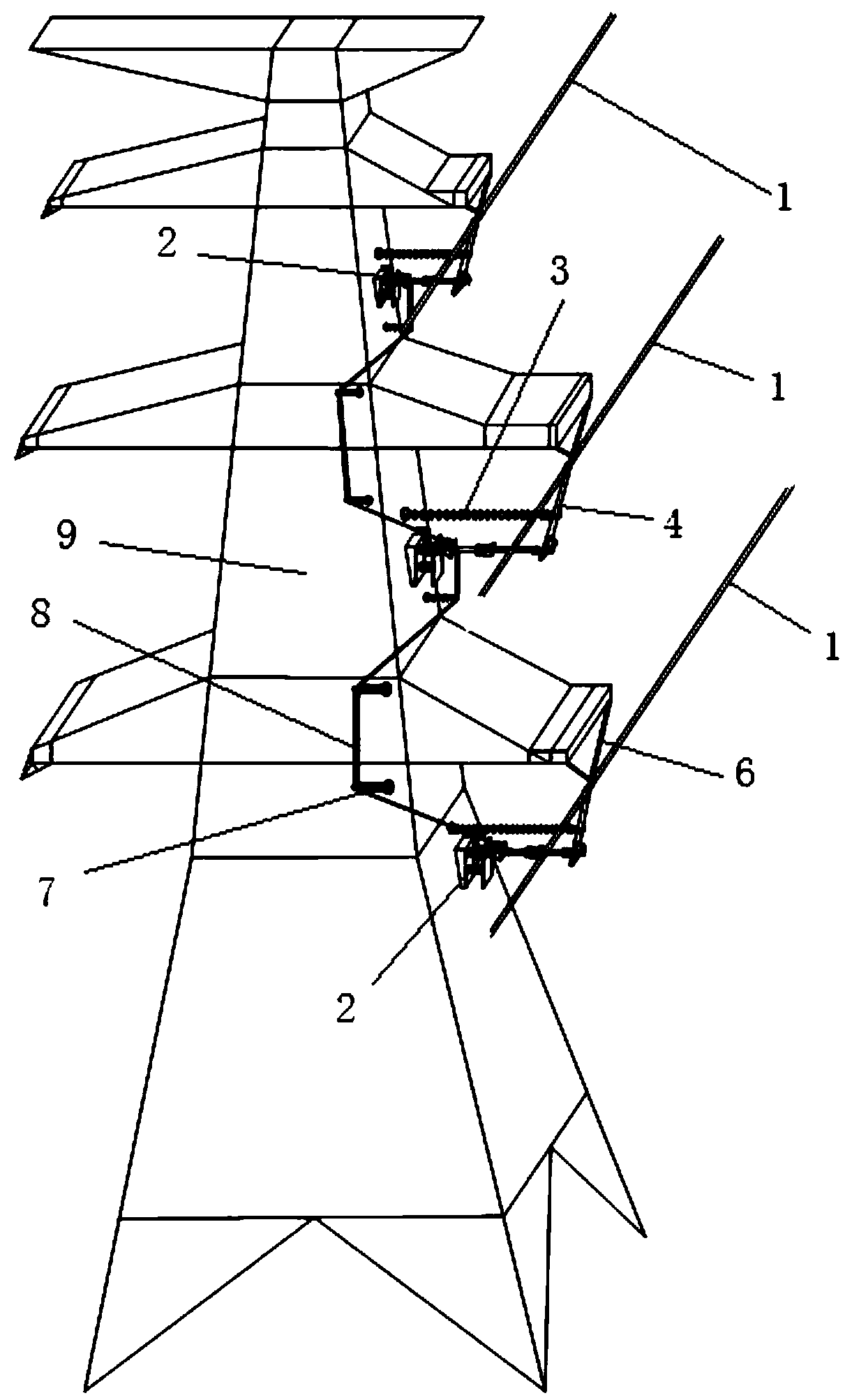
[0021] Example 1: as attached Figures 1 to 5 As shown, a DC ice melting short-circuit control structure includes an iron tower 9 and a power transmission wire 1. Three power transmission wires 1 are suspended on the iron tower 9 through an insulator string 6, and the lower part of the power transmission wire 1 is connected with a cable down Line 4, a horizontal protective insulator 3 is fixedly connected between the cable down conductor 4 and the iron tower 9, and a number of porcelain column insulators 7 are fixed on the side of the iron tower 9, between the iron tower 9 and the bottom end of the cable down conductor 4. A detachable and stackable control rod 2 is movably connected between the three control rods 2 , and a short-circuit wire 8 fixed on the porcelain column insulator 7 is connected between the three control rods 2 . There is a safe distance between the short-circuit wire 8 and the iron tower 9 .

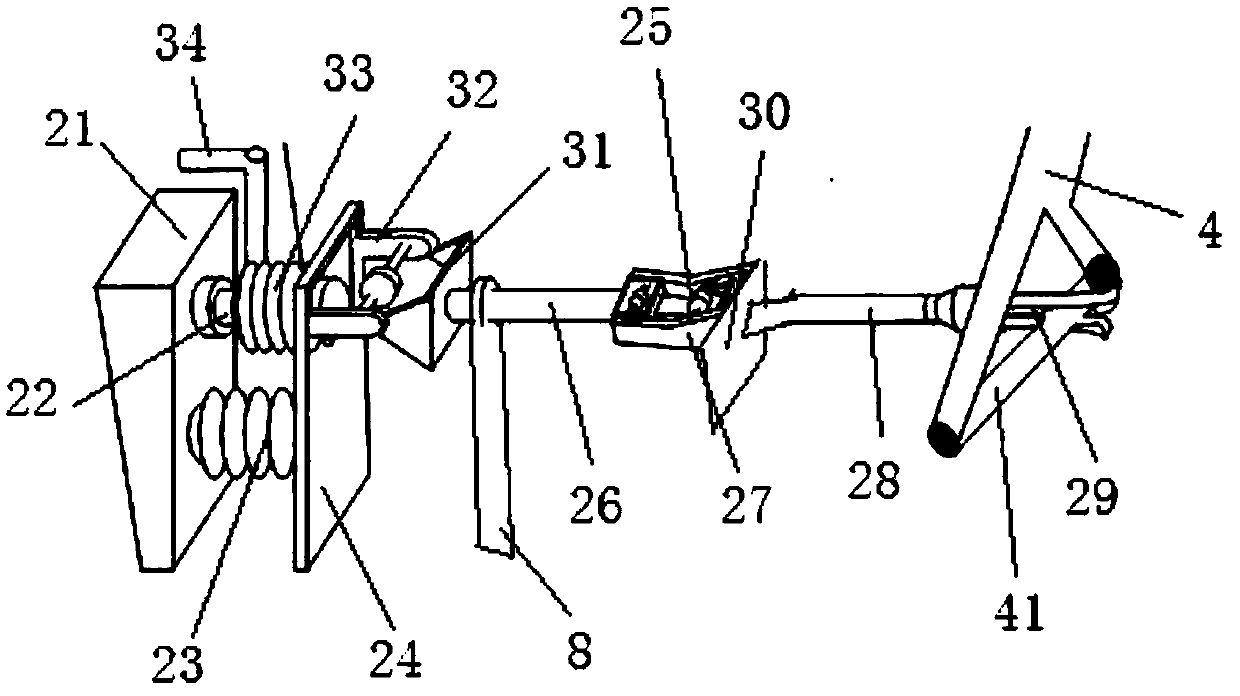
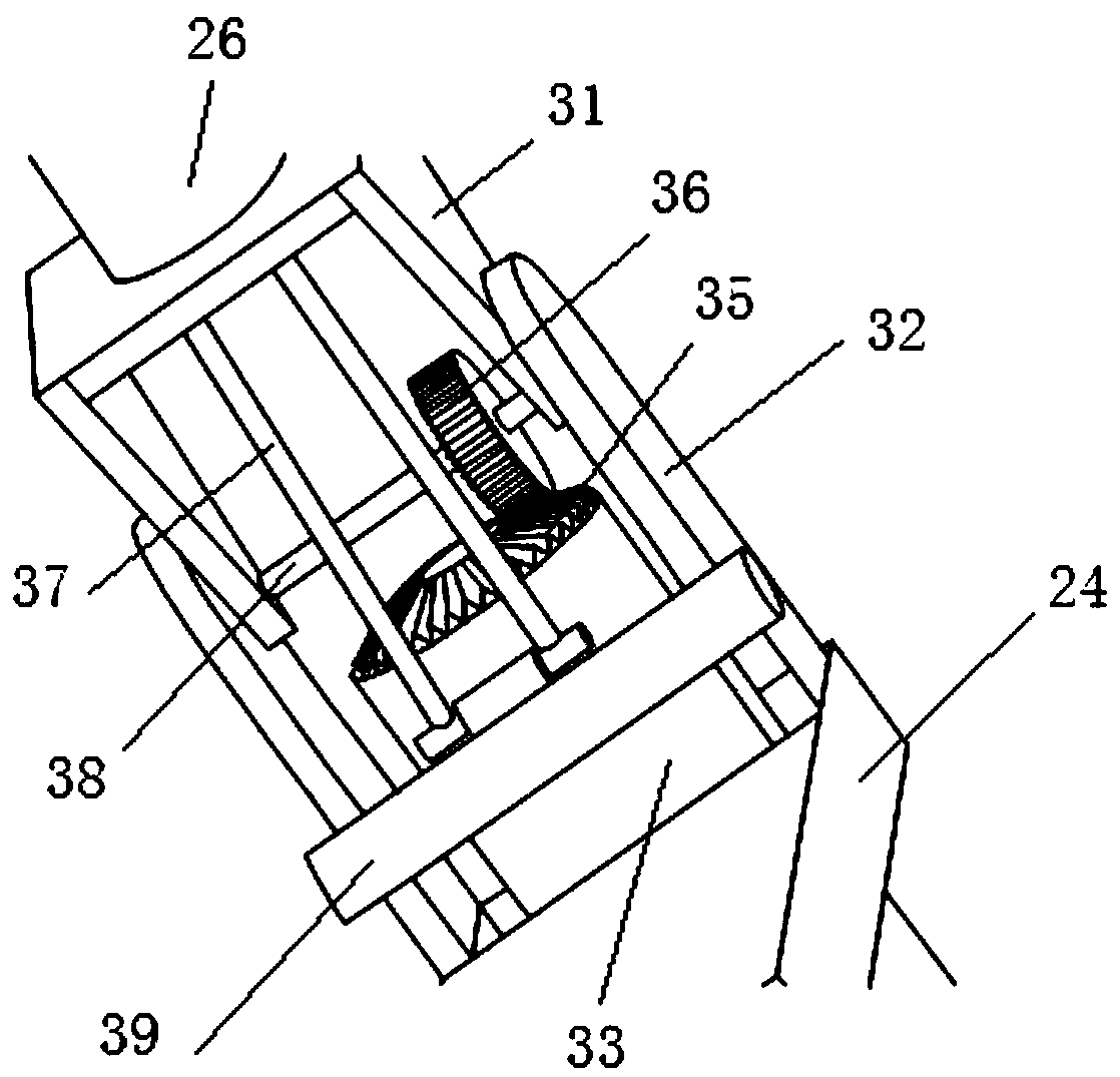
[0022] Further, the joystick 2 includes an insulating base 21 , ...


PUM


Abstract

The invention discloses a direct current ice-melting short-circuit control structure. The direct current ice-melting short-circuit control structure comprises an iron tower and three power transmission lines. The three transmission lines are suspended on the iron tower through insulator strings, and cable down leads are connected to the lower parts of the power transmission lines. Horizontal protective insulators are fixedly connected between the cable down leads and the iron tower, and a plurality of porcelain column insulators are fixed to the side edge of the iron tower. Detachable and foldable control levers are movably connected between the iron tower and the bottom ends of the cable down leads, a short-circuit wire fixed to the porcelain column insulators is connected between the three control levers, and a safety distance exists between the short-circuit wire and the iron tower. By arranging the three detachable, foldable and retractable control levers on the iron tower, the control levers are connected by the short-circuit wire, the purpose of being connected or disconnected with the power transmission lines in a short-circuit mode is achieved by the contraction or extension of the control levers, and a good use effect is obtained.

Description

technical field [0001] The invention relates to a direct current ice melting device, in particular to a direct current ice melting short-circuit control structure, and belongs to the technical field of transmission line equipment. Background technique [0002] There are two main methods for the existing DC ice-melting device to melt the ice of the transmission line. One is to directly energize the transmission line. The specific ice-melting steps are to first stop the transmission line, and then the electric worker climbs to the transmission line. Install the cable down-conductor on the line to short-circuit two or three phases of the three-phase transmission line, and finally energize and melt the ice. This solution can indeed remove ice on the transmission line, but this solution requires the operator to climb to the transmission line to install the cable down-conduct in harsh environments, which has a large safety hazard and takes a long time to perform the short-circuit ...

Claims


Application Information

Patent Timeline
IPC IPC(8): H02G7/16
CPCH02G7/16
Inventor 韦远武虢韬杨刘贵徐梁刚毕家启胡川黔韦荣照王时春严尔梅魏培权黄钰锡王坤辉
Owner GUIZHOU POWER GRID CO LTD
Why Eureka
Try Eureka