Heat-collecting de-icing device and method for ice-coating power transformation device

A technology of substation equipment and ice coating, applied in the direction of switchgear, electrical components, etc., can solve the problems of energy loss, light gathering, large volume, etc., and achieve the effect of real-time electrified ice melting, easy operation, and small volume

Active Publication Date: 2016-12-14
STATE GRID HUNAN ELECTRIC POWER +2
View PDF5 Cites 1 Cited by
  • Summary
  • Abstract
  • Description
  • Claims
  • Application Information

AI Technical Summary

Problems solved by technology

Devices that use thermal deicing need to use long insulated hot air pipes to achieve long-distance deicing work. In order to ensure the safety of ice melting, it requires a very high insulation performance of the insulating pipes, so the equipment of this type is usually large in size, resulting in Poor adaptability to small spaces
Although steam melting ice can also achieve good results, but because the spray is water vapor, it will inevitably reduce the insulation performance of the air gap, so usually only power failure can be used to remove ice, which limits its economic performance
[0003] Aiming at the ...

Method used


Image

  • Heat-collecting de-icing device and method for ice-coating power transformation device
  • Heat-collecting de-icing device and method for ice-coating power transformation device
  • Heat-collecting de-icing device and method for ice-coating power transformation device

Examples


Embodiment 1

[0045] Embodiment 1: Parabolic focusing type.

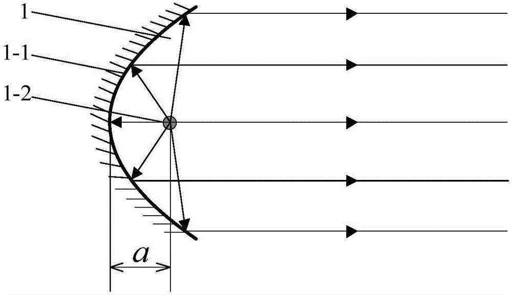
[0046] The concentrating unit is composed of an infrared heat lamp with a power of 0.7kW and a parabolic reflector.

[0047] 39 concentrating units 1 are arranged in a circular array on an inner fixed paraboloid 2 with a diameter of 2.5 meters. Adjust the installation angle so that the light beam of each converging unit 1 is perpendicular to the tangent plane of the internal fixed paraboloid 2 at this point, as attached Figure 4 shown. Wherein the focal length of the internal fixed paraboloid 2 is 6 meters, which is greater than the safety distance when melting ice. In this way, the light from the light concentrating unit 1 is gathered to the focal point of the internal fixed paraboloid 2, so that the ice-covered substation equipment 3 located at the focal point can be safely thawed. In this embodiment, the power of the ice-melting generator can reach 27.3kW.

Embodiment 2

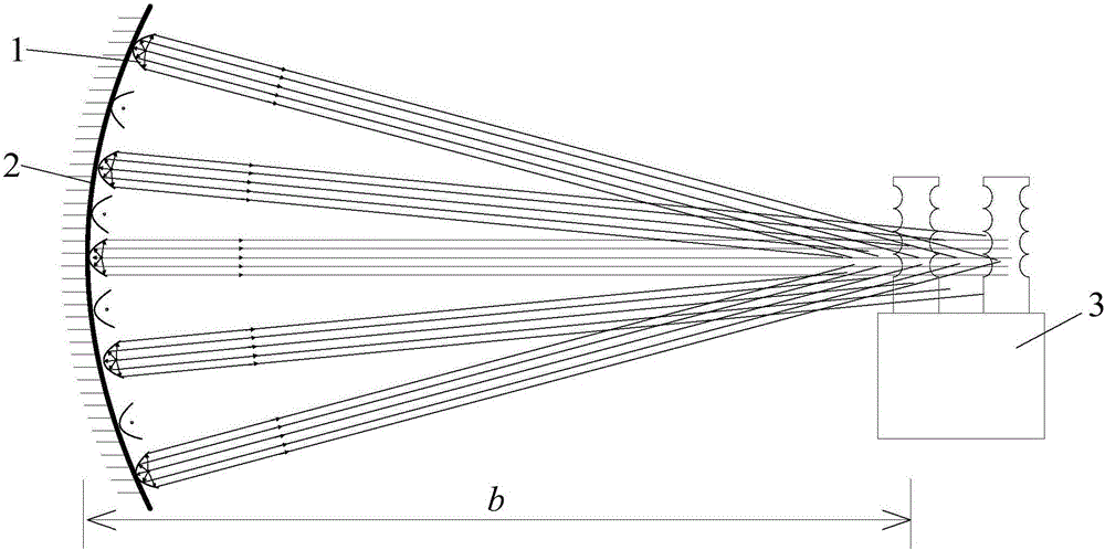
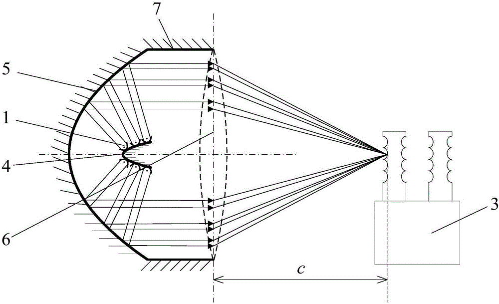
[0048] Embodiment 2: parabolic reflection + lens focus type.

[0049] The concentrating unit is composed of an infrared heat lamp with a power of 1.5kW and a parabolic reflector.

[0050] Because a single infrared lamp is difficult to meet the power demand, 20 concentrating units 1 are installed on the external fixed paraboloid 4, as shown in the attached image 3 shown. The outer fixed paraboloid 4 is located at the focus of the reflecting paraboloid 5 . Adjust the beam angle of the condensing unit 1 so that the beam is reflected by the reflective parabola 5 to become parallel light, and then transmitted by the convex lens 6 and focused to the focal point of the convex lens 6 . The space between the parabolic reflective surface 5 and the convex lens 6 is closed by a lamp wall 7, and the outer layer of the lamp wall 7 is coated with heat insulating material. The diameter of the convex lens 6 is 3 meters, and the focal length is 8 meters, which is greater than the safety dis...


PUM


Abstract

The invention discloses a heat-collecting de-icing device and method for an ice-coating power transformation device. The heat-collecting de-icing device comprises a plurality of light-gathering units; each light-gathering unit comprises a parabolic reflector and an infrared lamp; the infrared lamp is arranged on the focus of the parabolic reflector; light of the infrared lamp is reflected by the parabolic reflector to form a collimated light beam; several light-gathering units are configured in a way that several light-gathering units are installed on the internal surface of an internal fixed paraboloid dispersedly, the light beam emitted by each light-gathering unit is perpendicular to the tangent plane of the internal fixed paraboloid on the corresponding mounting point; the focal length b of the internal fixed paraboloid is larger than the safe distance when ice is melt; the ice-coating power transformation device is arranged on the focus of the internal fixed paraboloid; and therefore light of the light-gathering units are gathered to the focus of the internal fixed paraboloid, and safe ice melting can be carried out to the ice-coating power transformation device arranged on the focus. According to the invention, energy loss can be greatly reduced, and the ice-melting efficiency is improved.

Description

technical field [0001] The invention belongs to the technical field of disaster prevention and mitigation in electric power systems, and in particular relates to a heat-gathering and deicing device and method for ice-covered substation equipment. Background technique [0002] In southern my country, the winter is low temperature and rainy, and when the temperature is around zero, it is easy to form freezing rain. Freezing rain adheres to the surface of substation facilities and seriously damages the electrical and mechanical properties of the equipment. It is one of the most important natural disasters that threaten the safe and stable operation of the power grid. At present, there are complete sets of ice-melting technology and devices for power substation equipment at home and abroad. The ice-melting methods mainly include thermal deicing and steam melting. The former uses heated air to melt the ice layer, and the latter uses high-temperature saturated steam to melt or ev...

Claims


Application Information

Patent Timeline
IPC IPC(8): H02B3/00
CPCH02B3/00
Inventor 陆佳政刘毓李波方针罗晶章国勇何立夫
Owner STATE GRID HUNAN ELECTRIC POWER
Why Eureka
Try Eureka