
Automatic winding device and winding method for motor coil

An automatic winding and coil technology, applied in the direction of electric components, manufacturing motor generators, electromechanical devices, etc., can solve the problems of error-prone, low work efficiency, boring and repetitive work, etc., to avoid demoulding, improve production efficiency, wind Line process for quick and easy effects

Active Publication Date: 2020-03-20
ZHEJIANG JEAMO MOTOR
View PDF1 Cites 1 Cited by
  • Summary
  • Abstract
  • Description
  • Claims
  • Application Information

AI Technical Summary

Problems solved by technology

However, the efficiency of manual operation is low, time-consuming, boring and repetitive, and the product quality is affected by the proficiency of workers, especially when manually counting the number of winding turns. Since the motor needs to rotate forward and reverse continuously during winding, manual Errors often occur in counting, seriously affecting production efficiency
For example, the publication date is October 9, 2013, and the Chinese patent with the publication number CN102355097B discloses a motor coil winding device and a motor coil manufacturing method. low and error prone

Method used


Image

  • Automatic winding device and winding method for motor coil
  • Automatic winding device and winding method for motor coil
  • Automatic winding device and winding method for motor coil

Examples


Embodiment Construction

[0035] The present invention will be further described in detail below in conjunction with the accompanying drawings and examples. The following examples are explanations of the present invention and the present invention is not limited to the following examples.

[0036] Example.

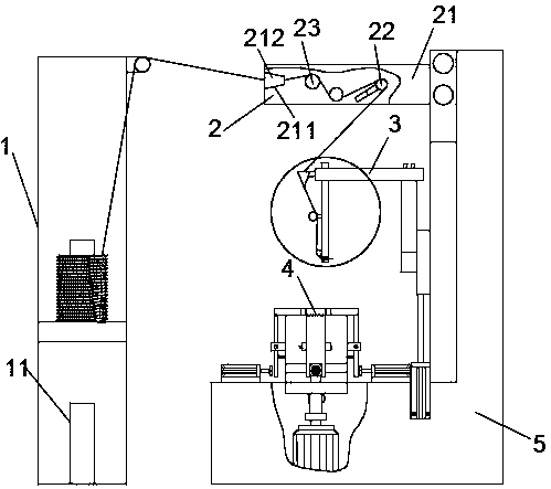
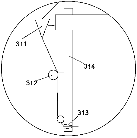
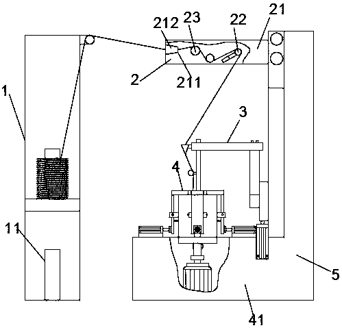
[0037] see Figure 1 to Figure 8 , the motor coil automatic winding equipment in the present embodiment comprises a coil frame 1, a wire inlet mechanism 2, a frame 5, a pinch-off mechanism 6 and a winding mechanism; the coil frame 1 is provided with several fixing piles 11; the pinch-off mechanism 6 is provided with the wire cutter of cutting copper wire. The winding mechanism includes a winding device 3 for clamping and winding copper wires and a winding die fixing device 4 for clamping and rotating the winding die; the action of the winding device 3 cooperates with the action of the winding die fixing device 4 .

[0038] The line feed mechanism 2 in the present embodiment comprises pulley fixe...


PUM


Abstract

The invention relates to automatic winding equipment and a winding method for a motor coil, which are mainly used for winding the motor coil and aim to solve the problems of low winding efficiency andeasy error in the prior art. The invention provides a technical scheme that the automatic winding equipment and the winding method for the motor coil. The automatic winding equipment for the motor coil comprises a coil frame, a wire feeding mechanism, a frame, a clamping and breaking mechanism and a winding mechanism; the winding mechanism comprises a winding device for clamping and winding copper wires, and a winding die fixing device for clamping and rotating the winding die; the winding device comprises a winding mechanical arm, a rotating wheel, a lifting module and a translation module;the winding die fixing device comprises a rotating motor, a bearing, a second rotating connecting component, a coil sleeve and a locking mechanism. According to the automatic winding equipment and thewinding method for the motor coil, winding is carried out by utilizing the lifting of the winding mechanical arm in the winding device and the rotary reciprocating of the winding die fixing device, so that the winding step is simplified into two single reciprocating processes, and the production efficiency is effectively improved.

Description

technical field [0001] The invention relates to a winding device and a winding method, in particular to a motor coil automatic winding device and a winding method. Background technique [0002] In the manufacturing process of the motor coil, the winding is generally performed by manually operating the winding machine. However, the efficiency of manual operation is low, time-consuming, boring and repetitive, and the product quality is affected by the proficiency of workers, especially when manually counting the number of winding turns. Since the motor needs to rotate forward and reverse continuously during winding, manual Errors often occur in counting, seriously affecting production efficiency. For example, the publication date is October 9, 2013, and the Chinese patent with the publication number CN102355097B discloses a motor coil winding device and a motor coil manufacturing method. Low and error-prone. Contents of the invention [0003] The purpose of the present in...

Claims


Application Information

Patent Timeline
Patent Type & Authority Patents(China)
IPC IPC(8): H02K15/04
CPCH02K15/0435
Inventor 朱春富沈宇功朱中杰李永兵王寿根
Owner ZHEJIANG JEAMO MOTOR
Learn More